


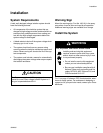

Installation
309293J 13
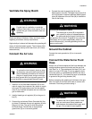
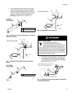
a. Graco WB100 Enclosure: Slide hose through
the strain relief fitting (W). Ensure conductive
layer (C) has passed through fitting. Tighten to
55 in-lb (6.2 N•m). Pull back on hose to check it
is secure. Comply with the requirements in
Warning at right. See F
IG. 6. and FIG. 7..
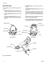
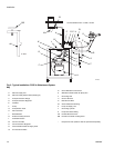
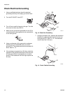
Fig. 6. Waterborne Hose Dimensions (At Graco
WB100 Enclosure)
Fig. 7. Shielded Fluid Hose Connection at Graco
WB100
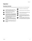
Fig. 8.
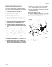
Fig. 9. Unshielded fluid connection
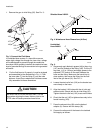
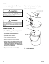
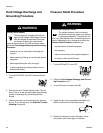
b. Non-Graco Isolated Enclosure: Connect hose
as instructed in the isolation system manual,
and comply with the requirements in the Warn-
ing at right. Refer to F
IG. 10..
Fig. 10. Shielded Fluid Hose Connection at Non-Gra-
co Isolated Enclosure
T
C
A 14.5 in. (368 mm)
B 0.75 in. (19 mm)
J
A
B
TI2166A
Shielded
Hose 245252
TI1897A
T
C
J
W
Z
L
See Warning at right.
T
C
A 12.0 in (305 mm)
J
A
TI2743A
Unshielded
Hose 246431
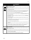
WARNING
Electric Shock Hazard
For Shielded hose systems:
Conductive hose layer (C) must be
grounded through its connection to the iso-
lation system’s grounded enclosure (L) or
grounded safety fence. To maintain grounding conti-
nuity, the conductive hose layer (C) must be engaged
in the ferrule when the strain relief nut is tightened.
Failure to properly install the hose in the strain relief
could result in an electric shock.
T
C
J
W
Z
L
See Warning below.
TI2744
A
TI1966A
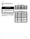
T
J
L
C (see note above)
NOTE: Ground layer (C) of hose must
be grounded at isolation system.