


Installation
309293J 15
245944 Fluid Regulator Kit
To add a fluid regulator to the Graco isolation system,
order Part No. 245944. See page 68 for the kit parts list.
1. Discharge the system voltage (page 20).
2. Relieve the pressure (page 20).
3. Open the isolated enclosure door.
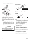
4. Remove the 1/4 OD tube (A1) from the pump air
inlet; see the tubing diagram on page 64.
5. Remove the waterborne fluid hose from the pump
fluid outlet fitting (231) and remove the fitting.
6. Unscrew the two pump mounting screws (S, F
IG.
12.) and remove the pump from the isolation enclo-
sure.
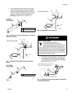
7. Remove the back of the control box (258).
8. Remove tube (A2) from elbow (282) at the air mani-
fold; see page 64. Install the Y fitting (506) in the
elbow. Install tubes (A2) and (507) into the Y fitting.
Route the tube (507) into the cabinet.
9. Replace the back of the control box (258).
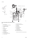
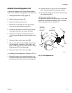
10. Assemble the fluid regulator kit as shown in F
IG. 12..
11. Reinstall the pump in the isolation enclosure. Use
the two mounting holes to the left of the holes used
previously, to allow clearance for the fluid regulator.
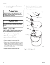
12. Connect tube (A1) to the air inlet of fluid regulator
(504). Connect tube (507) to the pump air inlet.
13. Connect the waterborne fluid hose to the fluid regu-
lator outlet fitting (501).
14. Return the system to service.
The cabinet air regulator and gauge (216, 217) will now
operate the air piloted fluid regulator (504). The pump
will now operate at the inlet air pressure.
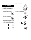
Fig. 12. Fluid Regulator Kit
TI2149A
501
502
503
504
505
506
507
Connect
tube A2
here
S
Tube A1
Connect
waterborne
fluid hose here
Connect to
elbow (282)
inside control
box (258)