


Parts
309293J 63
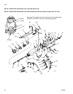
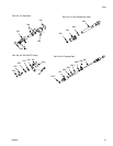
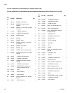
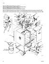
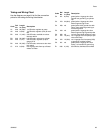
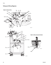
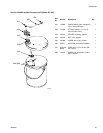
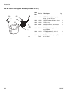
Tubing and Wiring Chart
Use the diagrams on page 64 to find the connection
points for the tubing and wiring listed below.
Code
Ref.
No.
Length
in. (mm)
Description
A1 248 20 (508) 1/4 OD tube, regulator to pump
A2 248 9 (229) 1/4 OD tube, regulator (216) to mani-
fold
B2 249 17 (432) 5/32 OD tube, manifold air to door
interlock switch
B3 249 20 (508) 5/32 OD tube, valve tee to cylinder
B4 249 5 (127) 5/32 OD tube, regulator (216) to
gauge (2170
B5 249 22 (559) 5/32 OD tube, valve tee to door inter-
lock switch
C1 272 9 (229) red 14 gauge wire from top of bleed
resistor to meter
C2 251 8 (204) green/yellow 14 gauge wire from
internal box ground lug to cylinder
cap
C3 273 34 (864) green/yellow 10 gauge wire from
external ground lug to cart
C4 239 n/a green/yellow 25 ft ground wire with
clamp, from external ground lug to
true earth ground
C5 243 n/a green/yellow 10 gauge wire from
external ground lug to ground probe
C6 226 n/a red wire from bleed resistor to pump
C7 272 16 (407) red 14 gauge wire from pump to pail
cover with clamp
C8 272 12 (305) red 14 gauge wire from pump (209)
to ground on cylinder bracket
C9 251 n/a green/yellow 10 gauge wire from
meter + to internal box ground lug
E1 286 4 (102) 3/8 OD tube, bulkhead to manifold
Code
Ref.
No.
Length
in. (mm)
Description