


308801 15
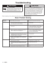
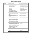
Basic Problem Solving
TYPE OF
PROBLEM
WHAT TO CHECK
If check is OK, go to next check
WHAT TO DO
When check is not OK, refer to this column
Electrical
(continued)
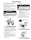
4. Check motor brushes for the following:
a. Loose terminal screws.
b. Broken or misaligned brush springs.
c. Brushes binding in holders.
d. Broken leads.
e. Worn brushes.
f. Brush leads snagged on spring clip.
NOTE: The brushes do not wear at same
rate on both sides of motor. Check both
brushes.
4. Refer to page 21.
a. Tighten.
b. Replace broken spring and/or align
spring with brush
c. Clean brush holders. Remove carbon
with small cleaning brush. Align brush
leads with slot in brush holder to as-
sure free vertical brush movement.
d. Replace brushes
e. Replace brushes if less than 0.5 in.
(12.5 mm) long.
f. Correctly route the wires.
See page 21.
5. Check motor armature commutator for burn spots,
gouges and extreme roughness. Remove motor
cover and brush inspection plates to check. See
page 21.
5. Remove motor and have motor shop
resurface commutator if possible.
See page 23.
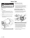
6. Check motor armature for shorts using armature
tester (growler) or perform motor test.
See page 20.
6. Replace motor. See page 23.
7. Check leads from pressure transducer and motor
to motor control board (22a) to be sure they are
securely fastened and properly mated.
7. Replace loose terminals; crimp to leads.
Be sure male terminal blades are straight
and firmly connected to mating part.
8. Check motor control board (22a) by performing
motor control board diagnostics on page 24. If
diagnostics indicate, substitute with a good board.
CAUTION: Do not perform this check until motor
armature is determined to be good. A bad motor
armature can burn out a good board.
8. Replace board. See page 24.
9. Check power supply cord (30). Disconnect black
and white power cord terminals; connect volt
meter to these leads. Plug in sprayer. Meter should
read 105–125 VAC. Unplug sprayer.
9. Replace power supply cord.
See page 25.
10. Check ON/OFF switch (80). Disconnect black wire
(96) between motor control board (22a) and switch
and connect volt meter between exposed terminal
switch and power cord’s white wire. Plug in
sprayer and turn ON. Meter should read 105–125
VAC. Turn off and unplug sprayer.
10. Replace ON/OFF switch. See page 25.
11. Check motor thermal cutout switch. Connect ohm-
meter between motor’s red leads. Meter should
read 1 ohm maximum.
11. Allow motor to cool. Correct cause of
overheating. If switch remains open after
motor cools, replace motor.
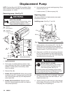
12. Check the transducer (67) by replacing it with a
new one.
12. Replace pressure transducer.
See page 28.
13. Check pressure adjustment potentiometer (77) by
replacing it with a new one.
13. Replace potentiometer.