


308801 17
Intermediate Problem Solving
TYPE OF
PROBLEM
WHAT TO CHECK
If check is OK, go to next check
WHAT TO DO
When check is not OK, refer to this column
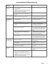
Low Output
(continued)
7. Check motor control board (22a) by substituting
with a good board.
CAUTION: Do not perform this check until motor
armature is determined to be good. A bad motor
armature can burn out a good board.
7. Replace board. See page 24.
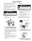
8. Check motor armature for shorts by using an arma-
ture tester (growler) or perform motor test. See
page 20.
8. Replace motor. See page 23
.
Drain Valve Leaks 1. Check drain valve for correct torque and/or worn
parts. Check for debris trapped on seat.
1. Tighten to 185 in-lb (21 Nm). Clean
valve and replace with new gasket (55)
and sealant 110–110. See page 30.
No Output: Motor
Runs And Pump
Strokes
1. Check paint supply. 1. Refill and reprime pump.
2. Check for clogged intake strainer. 2. Remove and clean, then reinstall.
3. Check for loose suction tube or fittings. See
page 29.
3. Tighten; use thread sealant on
npt threads of suction tube (43). Check
for damaged o–ring (45).
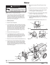
4. Check to see if intake valve ball and piston ball are
seating properly. See page 22.
4. Remove intake valve and clean. Check
ball and seat for nicks; replace as need-
ed. See page 22. Strain paint before us-
ing to remove particles that could clog
pump.
5. Check for leaking around throat packing nut
which may indicate worn or damaged packings.
See page 22.
5. Replace packings. See page 22. Also
check piston valve seat for hardened
paint or nicks and replace if necessary.
Tighten packing nut/wet-cup.
6. Release gun trigger. Observe resting position of
pump rod (222).
6. If pump consistently comes to rest
with rod (222) fully extended, the piston
packings and/or piston valve may be
worn. Service the pump. See page 22.
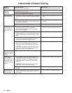
No Output: Motor
Runs But Pump
Does Not Stroke
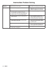
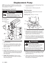
1. Check displacement pump connecting rod pin (14).
See Fig. 18, page 22.
1. Replace pin if missing. Be sure retainer
spring (15) is fully in groove all around
connecting rod.
2. Check connecting rod assembly (12) for damage.
See page 26.
2. Replace connecting rod assembly. See
page 26.
3. Be sure crank in drive housing rotates; plug in
sprayer and turn on briefly to check. Turn off and
unplug sprayer. See page 26.
3. Check drive housing assembly for dam-
age and replace if necessary. See
page 26.
Spray Pattern
Variations
1. Spray tip worn beyond sprayer pressure capability. 1. Replace spray tip.
NOTE: A smaller size tip will provide
longer life.
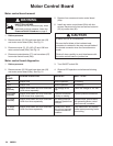
2. Check motor control board (22a) by performing
motor control board diagnostics on page 24. If
diagnostics indicate, substitute with a good board.
CAUTION: Do not perform this check until motor
armature is determined to be good. A bad motor
armature can burn out a good board.
2. Replace board. See page 24.