


308801 5
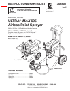
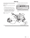
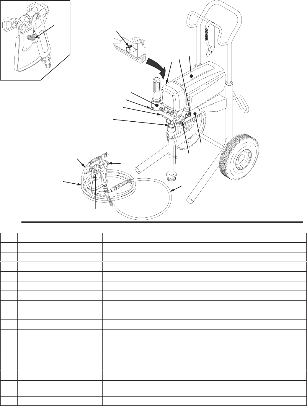
Component Function and Identification
7727A
03008
C
Fig. 1
E
F
D
A
G
J
L
R
M
N
B
H
S
K
P
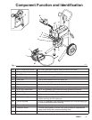
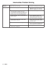
A Motor (Under shield shown) DC motor, permanent magnet, totally enclosed, fan cooled
B Pressure Adjusting Knob Controls fluid outlet pressure
C ON/OFF Switch Power switch that controls 120 VAC main power to sprayer
D Drive Assembly Transfers power from DC motor to the displacement pump
E Fluid Filter Filter of fluid between source and spray gun
F Fluid Outlet Main hose to spray gun is connected here
G Pail Hanger Container for fluid to be sprayed may be hung here
H Displacement Pump Transfers fluid to be sprayed from source through spray gun
J 50 ft (15 m) Main Hose 1/4 in. ID, grounded, nylon hose with spring guards on both ends
K RAC IV Tip Guard Reverse-A-Clean (RAC) tip guard reduces the risk of fluid injection injury
L Contractor Gun High pressure spray gun with gun safety latch
M RAC IV Switch Tip RAC switch tip uses high pressure fluid to remove clogs from spray tip
without removing tip from spray gun
N 3 ft (0.9 m) Hose 3/16 in. ID, grounded, nylon hose used between 50 ft hose and spray gun
to allow more flexibility when spraying
P Pressure Drain Valve Relieves fluid outlet pressure when open; diverts fluid to drain line
R Pressure Control Controls motor speed to maintain fluid outlet pressure at displacement
pump outlet. Works with pressure adjusting knob.
S Spray Gun Safety Latch Inhibits accidental triggering of spray gun