


28 308801
Pressure Transducer
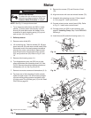
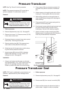
NOTE: See Fig. 23 and 24 for this procedure.
NOTE: The pressure transducer (67) cannot be re-
paired or adjusted. If it malfunctions, replace it.
Removal
WARNING
INJECTION HAZARD
To reduce the risk of serious injury, when
instructed to relieve pressure, follow the
Pressure Relief Procedure on page 8.
1. Relieve pressure.
2. Remove displacement pump (18). See page 22.
3. Remove front cover (11). Remove screws (25, 26).
Lower motor control card.
4. Disconnect harness connector from motor control
board (22a). Remove grommet (65).
5. Remove retaining ring (66). Pull pressure trans-
ducer down and out past drive housing (2).
6. Guide harness (A) through motor and drive hous-
ing and remove pressure transducer.
7. Inspect spacer (68) and seal (69) for damage.
Replace seal (69) only if it is cut, nicked, or if
leakage occurred. See page 28.
Installation
1. Using a small piece of solid copper or mild steel
wire (approximately 12 in.), form a small hook and
place it in the passage of bottom of the motor.
Guide it up and out the hole in the drive housing.
2. Pass a spacer (68) over harness connector (A)
and down into position at bottom of transducer
(67).
3. Guide harness up through leg and notch of drive
housing (2). Secure guide wire over connector.
4. While pulling guide wire out through bottom of
motor, guide harness through drive housing and
motor castings.
5. Place grommet (65) over harness and push into
position in drive housing hole.
6. Feed excess harness cable through grommet and
fully seat transducer body into hole in drive
housing leg. Secure it with retaining ring (66).
7. Attach connector to motor control board (22a).
Replace cover (11) and heat sink (22). Ensure no
wires are pinched between components.
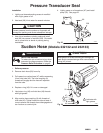
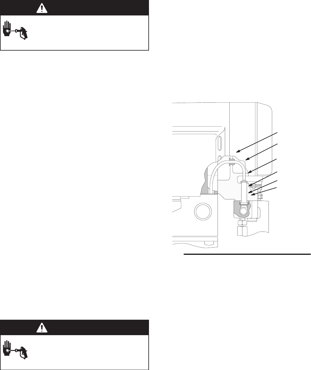
02996A
Fig. 24
67
65
66
A
68
69
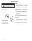
Pressure Transducer Seal
NOTE: PTFE seal is unaffected by most solvents and
materials. Replace seal only when leakage occurs.
Removal
WARNING
INJECTION HAZARD
To reduce the risk of serious injury, when
instructed to relieve pressure, follow the
Pressure Relief Procedure on page 8.
1. Relieve pressure.
2. Remove displacement pump (18). See page 22.
3. Remove seal (69) from recess in manifold (229).
4. Clean manifold recess with solvent and cloth or
cotton swabs. Inspect for nicks or scratches.