


7741A
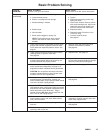
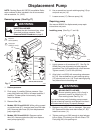
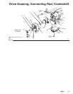
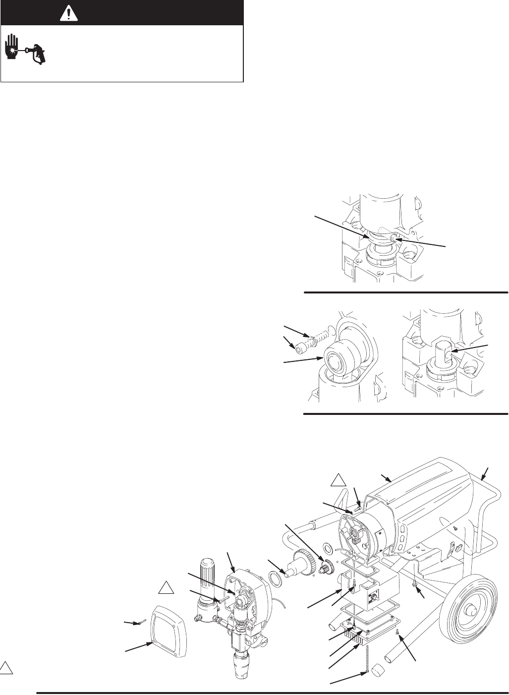
Fig. 21
1
16
4
11
34
20
25
5
13
2
32
4
3
75
Torque to 80 in-lb (9 Nm)
A
26
22
23
1
1
22a
70
308801 23
Motor
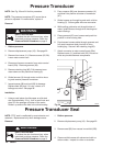
WARNING
INJECTION HAZARD
To reduce the risk of serious injury, when
instructed to relieve pressure, follow the
Pressure Relief Procedure on page 8.
NOTE: See Fig. 21 except where noted.
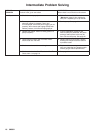
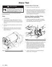
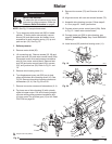
1. Try to stop pump with piston rod (222) in lowest
position. To lower piston rod manually, remove
shroud (32) and rotate motor fan blades. Use a
screwdriver to push retaining spring (15) up and
push out pin (14). See Fig. 19.
2. Relieve pressure.
3. Remove motor shield (32).
4. Lift connecting rod. Remove screws (25, 26) and
lower heat sink (22) and motor control board (22a).
Disconnect motor wires and pressure transducer
wire (A) from motor control board. Remove heat
sink (22) and motor control board (22a), screws
(23), and junction box (20). Refer to Fig. 21 and
13.
5. Remove drive housing cover (11).
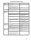
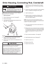
6. Turn displacement pump rod (222) so pin hole
aligns with bottom drive housing screw (16). See
Fig. 20. Remove three drive housing screws and
lockwashers (16, 4). See Fig. 20 and 21.
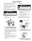
7. Remove two motor screws and lockwashers (3, 4).
8. Tap lower rear of drive housing (2) with a plastic
mallet to loosen motor. Pull drive housing straight
off motor while guiding pressure transducer wire
(A) from motor. Do not allow gear (13) to fall. Read
CAUTION on page 26.
9. Remove four screws (75) and lift motor off cart
(70).
10. Align new motor with cart and reinstall screws (75).
11. Assemble drive housing to motor. Follow steps 9
to 15 on page 26. Install junction box.
12. Connect wires to motor control board (22a). Refer
to Fig. 13. Install motor control board.
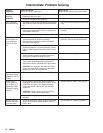
13. Connect piston rod (222) to drive housing; see
page 22, Installing Pump, Step 2 and WARNING
following it.
14. Install shroud (32) and drive housing cover (11).
15
14
Fig. 19
7840A
16
7840A
222
Fig. 20
4
12