


308801 25
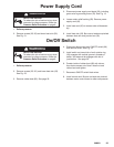
Power Supply Cord
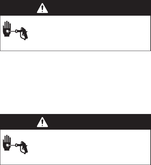
WARNING
INJECTION HAZARD
To reduce the risk of serious injury, when
instructed to relieve pressure, follow the
Pressure Relief Procedure on page 8.
1. Relieve pressure.
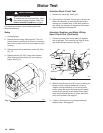
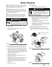
2. Remove screws (25, 26) and lower heat sink (22).
See Fig. 21.
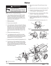
3. Disconnect power supply cord leads (30), including
green wire to grounding screw (78). See Fig. 13.
4. Loosen strain relief bushing (29). Remove power
supply cord (30).
5. Install new cord (30) in reverse order of disassem-
bly.
6. Install heat sink (22). Be sure no leads are pinched
between heat sink and junction box (20).
On/Off Switch
WARNING
INJECTION HAZARD
To reduce the risk of serious injury, when
instructed to relieve pressure, follow the
Pressure Relief Procedure on page 8.
1. Relieve pressure.
2. Remove screws (25, 26 ) and lower heat sink (22).
See Fig. 23.
3. Remove rubber boot (82). See page 32.
4. Disconnect black wires from ON/OFF switch (80)
and remove switch. See Fig. 13.
5. Install switch so internal tab of anti–rotation ring
(54) engages with vertical groove in threads of
switch, and external tab engages with slot of
junction box. See page 32.
6. Powder inside of rubber boot (82) with talcum,
then shake excess out of boot. Install nut and
rubber boot and tighten.
7. Reconnect ON/OFF switch black wires.
8. Install control card. Be sure no leads are pinched
between motor control board or other components.