


26 308801
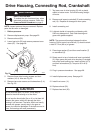
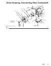
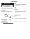
Drive Housing, Connecting Rod, Crankshaft
WARNING
INJECTION HAZARD
To reduce the risk of serious injury, when
instructed to relieve pressure, follow the
Pressure Relief Procedure on page 8.
NOTE: Inspect parts as they are removed. Replace
parts that are worn or damaged.
1. Relieve pressure.
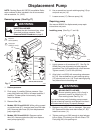
2. Remove displacement pump. See page 22.
3. Remove shroud (32).
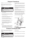
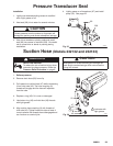
4. Lower heat sink (22) and remove pressure trans-
ducer (67). See page 28.
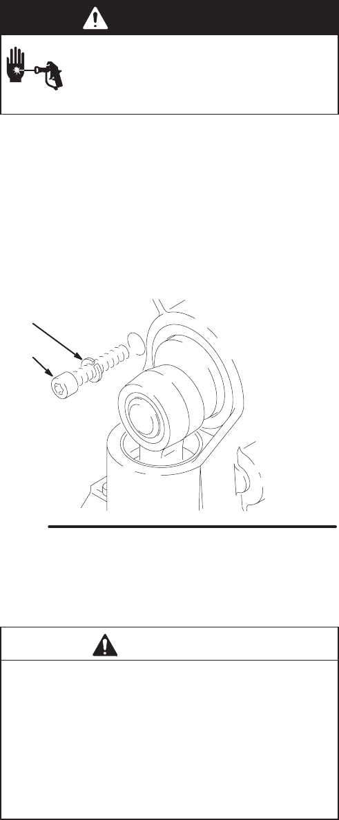
4
Fig. 22
7840A
16
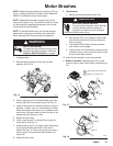
5. Remove three drive housing screws and lock-
washers (16, 4). Also see Fig. 23.
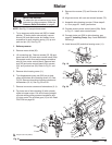
6. Remove two motor screws and lockwashers (3, 4).
See Fig. 23.
CAUTION
Do not allow the gear (13) to fall; it may stay at-
tached to the drive housing or to the motor.
Do not lose the thrust balls (2a or 41) or let them fall
between the gears, which will damage the drive
housing if not removed. The balls, which are heavily
covered with grease, usually stay in the gear re-
cesses, but could be dislodged. If the balls are not in
place, the bearings will wear prematurely.
7. Tap lower rear of drive housing (2) with a plastic
mallet to loosen motor. Pull drive housing straight
off motor.
8. Remove and inspect crankshaft (5) and connecting
rod (12). Replace all damaged or worn parts.
9. Install connecting rod.
10. Lubricate inside of connecting rod bearing with
SAE non-detergent oil. Pack roller bearing and
gears with grease supplied.
NOTE: The gears and bearings between the drive
housing (2) and motor front end bell (C) should contain
a total of 3 fl oz (89 cc) of grease.
11. Place large washer (6) and then small washer (7)
on crankshaft (5).
12. Rotate crank to top of stroke and insert crankshaft
(5). Align gears and push drive housing (2) straight
onto motor and locating pins. Install screws (16, 3)
and their lockwashers (4). Torque to 80 in-lb (9
Nm).
13. Plug in pressure transducer. See page 28.
14. Install displacement pump. See page 22.
15. Install front cover (11).
16. Replace shroud (32).
17. Replace heat sink (22).