


14ą307-586
Service
WARNING
INJECTION HAZARD
T
o reduce the risk of a fluid injection
injury
, follow the
Pressure Relief Proce
-
dure
on page 7 before checking or
servicing any of the system equipment and when
-
ever you are instructed to relieve pressure.
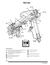
NOTE:
D
Follow the
Service Notes
in Fig. 8 when reassem
-
bling the gun. Also refer to the parts drawing on
page 16 for parts not shown in Fig. 8.
D
Gun Repair Kit 224–949 is available. See page 17.
The reference numbers with asterisks in the service
procedures are included with the kit.
Air
V
alve Service
1. Relieve
the pressure as instructed on page 7.
2.
Remove the trigger (3) and valve cap (1
1). See the
parts drawing and Fig. 8.
3.
Unscrew the needle nut (49) while holding the flats
of the air valve (52*) stem with a long nose pliers.
CAUTION
T
o avoid leakage, be careful not to scratch the air
valve stem.
4.
Remove the spring (10*) and air valve (52*).
5.
If there is air leakage at the air valve (52), unscrew
the packing nut (50) and carefully remove the
u-cup packing (51*). Replace the packing if it is
worn or damaged. When re-installing, be sure the
u-cup faces inward.
6.
If leakage occurs internally or the front of the gun
leaks air when it is not triggered, clean and inspect
the air valve and the spring for wear or damage.
Replace as needed.
7.
For the best air valve life, lubricate the external air
valve shaft (point A) with light oil after each day’
s
use.
Fluid Packing Replacement
Follow
the procedure below to remove the fluid pack
-
ings for cleaning or replacement and to inspect the
needle shaft when there is leakage from the back of
the needle.
1.
Relieve the pressure as instructed
on page 7.
2.
Remove the air cap retainer (25), air cap (27),
spray tip (28), and air separator (32). See Fig. 8.
3. T
rigger the gun to back the fluid needle ball of
f the
seat. Remove the dif
fuser-seat (30*) and gasket
(33*). Install a new gasket.
4.
Remove the trigger (3). See the Parts Drawing,
page 16.
5.
Remove the hex nut (21*) from the fluid needle
(5*), while holding the square part of the fluid
needle.
6.
Pull the fluid needle (5) and compression spring
(24*) from the front of the gun.
7. T
o remove the old packings (47*), insert the pack
-
ing tool (55*) into the front of the gun and screw it
into the packings. Pull the packings from the front
of the gun.
8.
Clean the parts with a compatible solvent and a
soft brush. Inspect the fluid needle (5) for wear or
damage, and replace it if necessary
.
9.
Insert the new packings (47) onto the fluid needle
(5) shaft as shown in Detail D of Fig. 8.
10.
Install the fluid needle (5). Do not damage the
packings.
11.
Screw the hex nut (21) all the way onto the fluid
needle (5). Do not over-tighten it.
12.
Install the trigger
.
13. T
rigger the gun while screwing the dif
fuser-seat
(30) back into the gun. T
orque the dif
fuser-seat to
23 to 27 ft-lbs (31 to 37 N
Sm).
14.
Install the air separator (32), spray tip (28), air cap
(27), and air cap retainer (25).