


18ą307-586
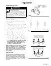
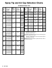
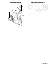
Spray
T
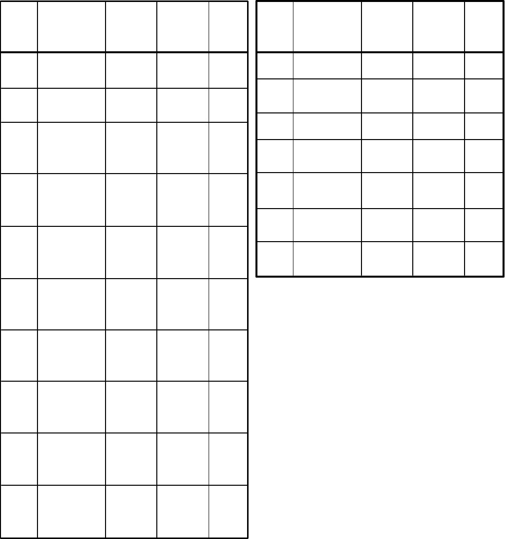
ip and Air Cap Selection Charts
*Light
to
Orifice
Inches (mm)
Medium *Heavy
Size
Fan W
idth Viscosity Viscosity
inches
at 12”
fl oz/min fl oz/min
Part
(mm)
(300 mm)
(liters/min) (liters/min)
No.
**0.027
8–10 (200–250)
58.5
50.0
182–427
(0.689)
12–14 (300–350)
(1.7) (1.4) 182–627
**0.029
8–10 (200–250)
68.0 59.0 182–429
(0.737)
12–14 (300–350)
(1.9) (1.7) 182–629
14–16 (350–400)
182–729
**0.031
8–10 (200–250)
78.0
69.0
182–431
(0.787) 12–14(300–350) (2.2) (2.0) 182–631
**0.035
8–10 (200–250)
98.0 89.0
182–435
(0.889)
10–12 (250–300)
(2.8) (2.5) 182–535
12–14 (300–350)
182–635
**0.039
8–10 (200–250)
1
18.0 109.0
182–439
(0.991)
10–12 (250–300)
(3.4) (3.1) 182–539
12–14 (300–350)
182–639
**0.041
8–10 (200–250)
138.0 129.0
182–441
(1.041)
10–12 (250–300)
(4.0) (3.7) 182–541
12–14 (300–350)
182–641
**0.043
8–10 (200–250)
158.0 149.0
182–443
(1.092)
10–12 (250–300)
(4.6) (4.3) 182–543
12–14 (300–350)
182–643
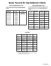
*Light to
Orifice
Inches (mm)
Medium *Heavy
Size
Fan W
idth Viscosity Viscosity
inches
at 12”
fl oz/min
fl oz/min
Part
(mm)
(300 mm)
(liters/min) (liters/min)
No.
0.007
2–4 (50–100)
4.0 182–107
(0.178)
4–6 (100–150)
(0.1) 182–207
6–8 (150–200)
182–307
0.009
4–6 (100–150)
7.0 182–209
(0.229)
6–8 (150–200)
(0.2) 182–309
8–10(200–250) 182–409
0.011
4–6 (100–150)
10.0 182–211
(0.279)
6–8 (150–200)
(0.3) 182–311
8–10 (200–250)
182–411
10–12 (250–300)
182–511
12–14 (300–350)
182–611
0.013
4–6 (100–150)
13.0 182–213
(0.330)
6–8 (150–200)
(0.4) 182–313
8–10 (200–250)
182–413
10–12 (250–300)
182–513
12–14 (300–350)
182–613
0.015
4–6 (100–150)
17.0 182–215
(0.381)
6–8 (150–200)
(0.5) 182–315
8–10 (200–250)
182–415
10–12 (250–300)
182–515
12–14 (300–350)
182–615
0.017
4–6 (100–150)
22.0 17.0
182–217
(0.432)
6–8 (150–200)
(0.7) (0.5) 182–317
8–10 (200–250)
182–417
10–12 (250–300)
182–517
12–14 (300–350)
182–617
0.019
6–8 (150–200)
28.0 21.0
182–319
(0.483)
8–10 (200–250)
(0.8) (0.6) 182–419
10–12 (250–300)
182–519
12–14 (300–350)
182–619
14–16 (350–400)
182–719
0.021
8–10 (200–250)
35.0
27.0
182–421
(0.533)
10–12 (250–300)
(1.0) (0.8) 182–521
12–14 (300–350)
182–621
14–16 (350–400)
182–721
16–18 (400–460)
182–821
0.023
8–10 (200–250)
40.0 34.0
182–423
(0.584)
10–12 (250–300)
(1.2) (0.97) 182–523
12–14 (300–350)
182–623
14–16 (350–400)
182–723
16–18 (400–460)
182–823
0.025
8–10 (200–250)
50.0 42.0
182–425
(0.635)
10–12 (250–300)
(1.5) (1.2) 182–525
12–14 (300–350)
182–625
14–16 (350–400)
182–725
16–18 (400–460)
182–825
*
Fluid output at 600 psi (41 bar).
**
Requires air cap 218–336.
Fluid
output (Q) at other pressures (P) can be calculated by this
formula: Q = (0.041) (QT) (q''
).
Where
QT = Fluid output (fl oz/min) from the above table for
the
selected orifice size.
NOTE:
Other tips are available on special work order
. Allow 4
to 6 weeks for delivery
.
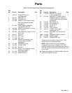
STANDARD
SPRA
Y
TIPS
P