


4ą307-586
Installation
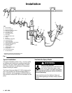
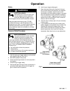
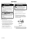
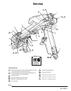
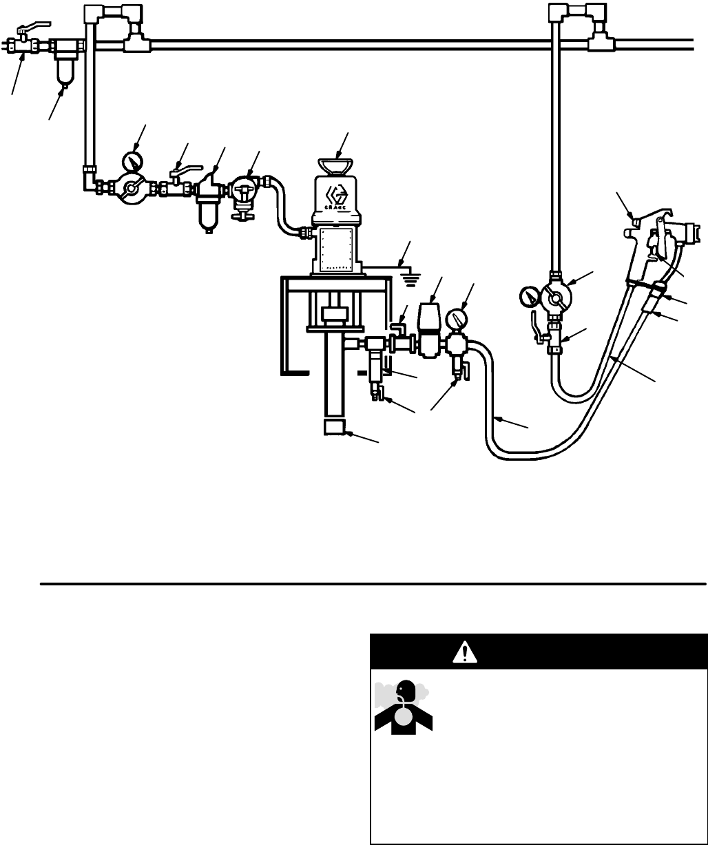
KEY
A Air
Line Filter
B
Air Line Lubricator
C*
Bleed–type Master Air V
alve
D
Pump Air Regulator
E*
Fluid Drain V
alve
F
Fluid Shutof
f V
alve
G
Fluid Filter
H*
Grounded Fluid Hose
J Pump
K
Air Line
L
Air Pressure Regulator
M
Pump Fluid Inlet
N
In–line Fluid Filter
P
Pattern Adjustment Valve Knob
Q
Fluid Pressure Regulator
R
Pressure Gauge
ST
rigger Safety
T
Pump Runaway V
alve
V*
Ground Wire
W
Gun Fluid Connector
X
Air Shutof
f V
alve
*Equipment required for safe operation of the
system. Must be purchased separately
.
Fig.
1
C
A
D
C
B
T
J
V
F
Q
R
G
E
M
H
L
X
K
N
W
S
P
Typical Installation
The
typical installation shown in Fig. 1 is only a guide
for selecting and installing air-assisted airless spray
systems. It is not an actual system design. Contact
your Graco distributor for assistance in designing a
system to meet your needs.
The Graco fluid pump Model 217–523 is designed for
use in high pressure air-assisted airless systems. It
has a maximum working pressure of 950 psi (66 bar).
See instruction manual 307–595 for information on this
pump.
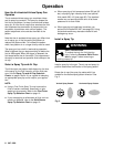
Ventilate the Spray Booth
WARNING
TOXIC
FLUID HAZARD
T
o prevent hazardous concentrations of
toxic and/or flammable vapors, spray
only in a properly ventilated spray booth.
Never operate the spray gun unless ventilation
fans are operating.
Check and follow all of the National, State and
Local codes regarding air exhaust velocity require
-
ments.