


307-586 5
Installation
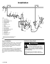
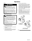
Connect the Air Line
1. Install
an air line filter (A) to ensure a clean, dry air
supply to the gun. Dirt and moisture in the line can
ruin the appearance of your finished piece. See
Fig. 1.
2.
Install an air pressure regulator (L) on the gun air
supply line to control the air pressure to the gun.
3.
Install an air pressure regulator (D) on the pump
air supply line to control air pressure to the pump.
4.
Install a bleed-type air shutof
f valve (C) on the
main air line and on the pump air line, downstream
of the pump air regulator
, to shut of
f air to the
pump. Install an additional bleed-type valve on
each pump air supply line to relieve air trapped
between this valve and the pump after the air
regulator is shut of
f.
WARNING
The bleed-type air shutof
f valve is required in your
system to relieve air trapped between this valve
and the pump after the air regulator is closed.
T
rapped air can cause the pump to cycle unexpect
-
edly
, which could result in serious injury
.
NOTE:
The gun air inlet has a 1/4–18 npsm (R1/4–19)
compound male thread that is compatible with NPSM
and BSP female swivel connectors.
5.
Install an air shutof
f valve (X) on each gun air
supply line, downstream of the gun air regulator, to
shut of
f air to the gun(s).
6.
Connect the air hose (K) from the air supply to the
gun air inlet.
Connect the Fluid Line
WARNING
INJECTION
HAZARD
T
o reduce the risk of property damage or
serious injury
, including fluid injection,
which could be caused by component
rupture or unrelieved fluid pressure,
D
A fluid drain valve(s) (E) is required in your
system to assist in relieving fluid pressure in the
displacement pump, hose and gun; triggering
the gun to relieve pressure may not be suf
fi-
cient.
D
A fluid pressure regulator (Q) must be installed
in the system if the pump’
s maximum working
pressure exceeds the gun’s maximum fluid
working pressure of 950 psi (66 bar).
1.
Install a fluid filter (G) and drain valve(s) (E) close
to the pump’
s fluid outlet. The drain valve assists
in relieving fluid pressure in the displacement
pump, hose, and gun. See Fig. 1.
2.
Install a fluid pressure regulator (Q) to control fluid
pressure to the gun.
NOTE:
Some applications require fine-tuned control of
fluid pressure. Y
ou can control fluid pressure more
accurately with a fluid pressure regulator than by
regulating the air pressure to the pump.
3.
Install a fluid shutof
f valve (F) to shut of
f the fluid
supply to the gun.
4.
Install fluid drain valve(s) (E) close to the pump’
s
fluid outlet.
NOTE:
The gun fluid fitting (W) has a 1/4–18 npsm
(R1/4–19) compound male thread that is compatible
with NPSM and BSP female connectors.
5.
Install an in-line fluid filter (N) on the gun fluid
fitting (W) to avoid clogging the spray tip with
particles from the fluid.
6.
Connect the grounded fluid hose (H) to the gun
fluid fitting (W) or optional in-line filter (N).