


17
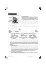
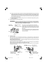
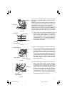
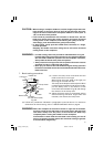
Ink lining can be easily made on this tool to the
laser marker. A switch lights up the laser marker.
(Fig. 20)
Depending upon your cutting choice, the laser line
can be aligned with the left side of the cutting width
(saw blade) or the ink line on the right side.
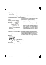
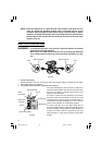
The laser line is adjusted to the width of the saw
blade at the time of factory shipment. Adjust the
positions of the saw blade and the laser line taking
the following steps to suit the use of your choice.
Fig. 20
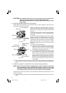
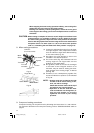
(1) Light up the laser marker and make a groove
of about 5mm (3/16") deep on the workpiece
that is about 20mm (25/32") in height and
150mm (5-29/32") in width. Hold the grooved
workpiece by vise as it is and do not move it.
For grooving work, refer to "11.Groove cutting
procedures" on page 27.
Fig. 21
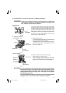
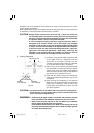
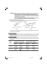
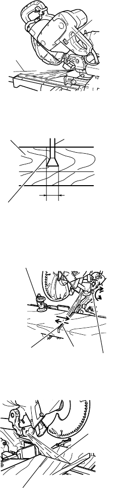
(2) Then, turn the adjuster and shift the laser line.
(If you turn the adjuster clockwise, the laser
line will shift to the right and if you turn it
counterclockwise, the laser line will shift to the
left.) When you work with the ink line aligned
with the left side of the saw blade, align the
laser line with the left end of the groove. (Fig.
22) When you align it with the right side of the
saw blade, align the laser line with the right
side of the groove.
Fig. 22
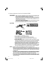
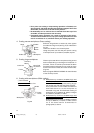
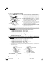
(3) After adjusting the position of the laser line,
draw a right-angle ink line on the workpiece
and align the ink line with the laser line. When
aligning the ink line, slide the workpiece little
by little and secure it by vise at a position where
the laser line overlaps with the ink line. Work
on the grooving again and check the position
of the laser line. If you wish to change the laser
line's position, make adjustments again
following the steps from (1) to (3).
Fig. 23
Switch
Laser line
Saw Blade
Marking
(pre-marked)
Workpiece
Cutting Width
Vise Assembly
Turn
Move
Laser Line
Groove
Adjuster
Laser Line
Marking
(pre-marked)
01Eng_C10FSH_Eng 3/29/07, 12:30 PM17