


18
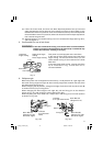
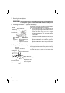
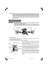
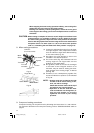
NOTE: Check and make sure on a periodic basis if the position of the laser line is in
order. As regards the checking method, draw a right-angle ink line on the
workpiece with the height of about 20mm (25/32") and the width of 150mm
(5-29/32"), and check that the laser line is in line with the ink line [The deviation
between the ink line and the laser line should be less than the ink line width
(0.5mm)]. (Fig. 23)
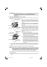
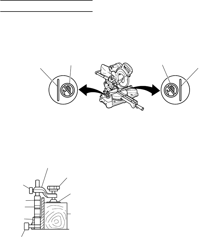
PRACTICAL APPLICATIONS
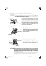
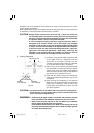
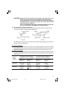
WARNING: * To avoid personal injury, never remove or place a workpiece on the table
while the tool is being operated.
* Never place your limbs inside of the line next to warning sign while the
tool is being operated. This may cause hazardous conditions (see Fig.
24).
Fig. 24
1. Switch operation
Switch operation the tool is turned on when the switch trigger is pulled and off when
the trigger switch is released.
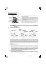
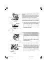
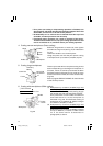
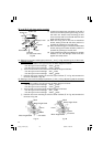
2. Using the Vise Assembly (Standard accessory)
The vise assembly can be mounted on either the
left fence (Fence (B)) or the right fence (Fence (A)),
and can be raised or lowered according to the
height of the workpiece.
To raise or lower the vise assembly, first loosen
the 6mm knob bolt. As shown in Fig. 25, the vise
shaft has three locking grooves into which the tip
of the 6mm wing bolt is designed to fit in order to
lock the screw holder in the desired position.
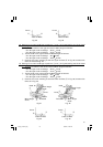
To ensure that the tip of the 6mm wing bolt is
properly aligned with the desired locking groove
on the vise shaft, simply align the upper surface of
the fence to either of three v-grooves on the vise
shaft surface or to the lower surface of the screw
holder.
Warning Sign
Line
Warning Sign
Line
Fig. 25
Screw Holder
Knob
Workpiece
Vise Plate
Groove
6mm
Knob Bolt
Fence
6mm Knob Bolt
V-Groove
01Eng_C10FSH_Eng 3/29/07, 12:30 PM18