


27
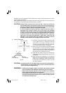
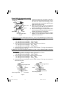
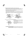
CAUTION: Always confirm that the motor head (see Fig. 1) does not contact the
crown molding vise ass’y when it is lowered for cutting. If there is any
danger that it may do so, loosen the 6mm knob bolt and move the crown
molding vise ass’y to a position where it will not contact the saw blade.
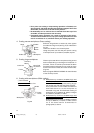
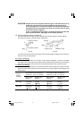
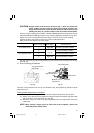
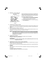
Position crown molding with its WALL CONTACT EDGE against the guide fence and its
CEILING CONTACT EDGE against the crown molding Stoppers as shown in Fig. 45-b.
Adjust the crown molding Stoppers according to the size of the crown molding.
Tighten the 6mm wing bolt to secure the crown molding Stoppers.
Refer to the lower table for the miter angle.
Use the sub fence (A) (optional accessories) to secure the crown molding more firmly.
(see Fig. 15)
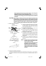
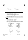
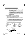
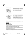
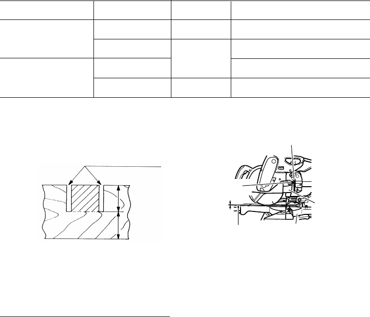
11. Groove cutting procedures
Fig. 46 Fig. 47
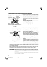
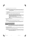
Grooves in the workpiece can be cut as indicated in Fig. 46 by adjusting the 8mm depth
adjustment bolt.
Cutting depth adjustment procedure:
(1) Loosen the 8mm wing nut and turn the 8mm depth adjustment bolt by hand.
(2) Adjust to the desired cutting depth by setting the distance between the saw blade
and the surface of the base (see b in Fig. 46).
(3) The 8mm wing nut must be properly tightened after the adjustment has been
completed.
NOTE: When cutting a single groove at either end of the workpiece, remove the
unneeded portion with a chisel.
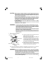
Position in Fig. 35 Miter angle Finished piece
For inside corner 1 Right 45° Save the right side of blade
2
Left 45°
Save the left side of blade
For outside corner 3 Save the right side of blade
4 Right 45° Save the left side of blade
8mm Depth
Adjustment Bolt
8mm Wing Nut
Bottom Line of
the Groove
Turntable
b
Gear Case
a
b
Cut grooves with
saw blade
01Eng_C10FSH_Eng 3/29/07, 12:30 PM27