


12
English
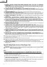
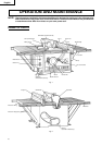
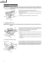
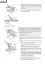
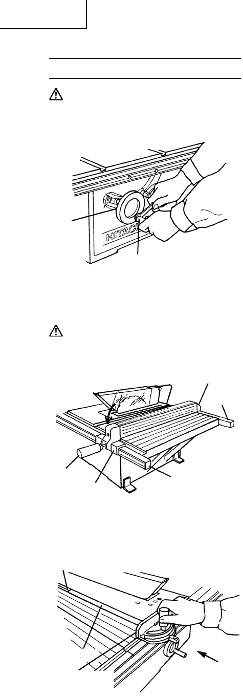
Fig. 6
Handle Bar
Wheel
Grip
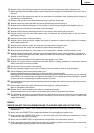
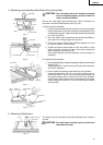
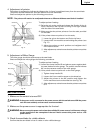
Fig. 7
Support
Rear Rail
Front Rail
Width Body
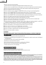
Miter Gauge Groove
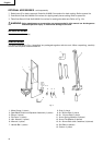
Sheet Bar
Miter Gauge
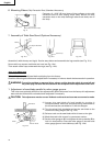
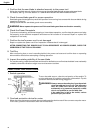
Fig. 8
ASSEMBLY PROCEDURES
WARNING:To avoid an accident or personal injury, always confirm that the switch is turned OFF and
the power plug has been disconnected from the receptacle before assembly of this tool.
1. Assembly of Handle Bar
The handle bar allows faster turning of the wheel.
When properly assembled it with rotate freely but with only a
small amount of play,
(1) Tighten the screw of the handle bar until it hits against the
wheel.
(2) Securely tighten the handle bar nut with a wrench.
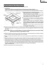
2. Installing of Rip Fence
CAUTION: The rip fence must be aligned parallel to the saw blade to minimize the kickback (refer to
page 19).
The rip fence can be conveniently used to cut a workpiece into
different pieces of precise width or into parallel pieces. It can be
mounted on either the right or left side of the table.
(1) Tighten the screw of the grip.
(2) Catch the hook of the support in the bottom part of the rear
rail.
(3) Lower the rip fence in the arrow direction, and fit the part of
the width body and support to the groove of the front and
rear rail.
(4) Confirm that the rip fence is moved right and left and it moves
smoothly.
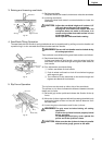
3. Assembly of Miter Gauge
The miter gauge is convenient for cutting long or angular pieces
which are difficult to work on with the rip fence. It can be mounted
on either the right or left side of the table. Align the sheet bar of
miter gauge with the miter gauge groove and slide it in the
direction indicated by the arrow through the front of the table.