


15
English
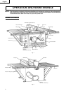
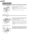
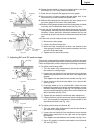
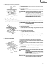
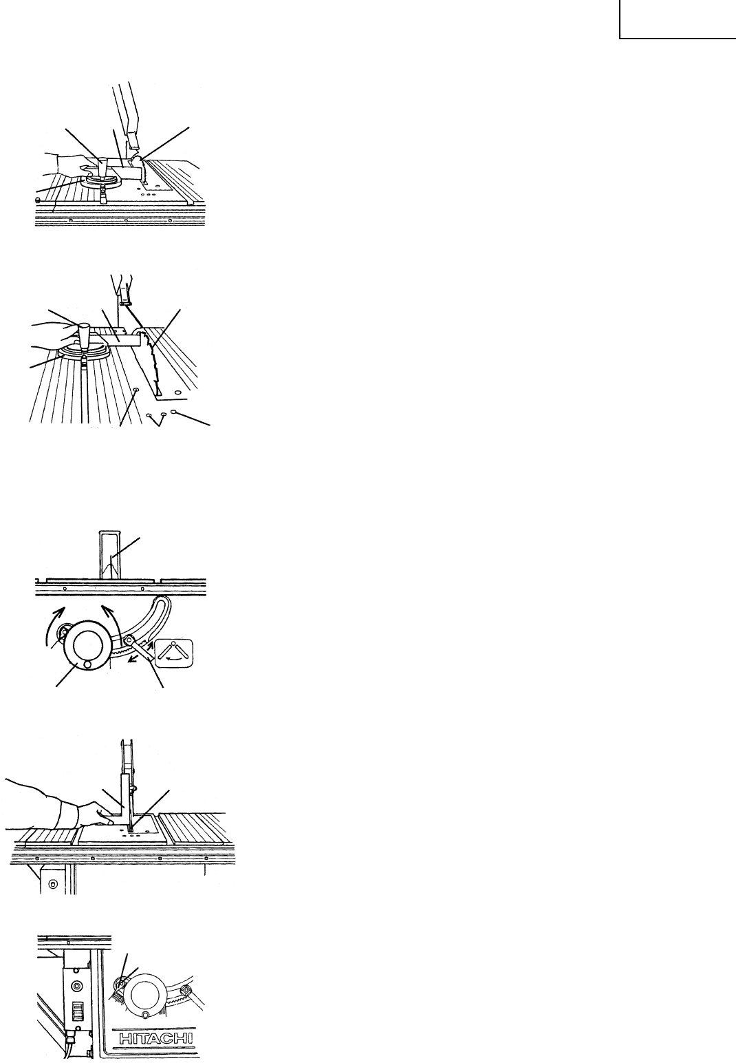
(6) Rotate the saw blade to bring the marked tooth in the front
and about 1/2" (12.7 mm) above the table top.
(7) Place the bar of square flat against the miter gauge.
(8) Move the bar of square toward the saw blade until it just
touches the tip of the marked saw blade tooth.
(9) Without disturbing the bar clamped to the miter gauge, move
the miter gauge to the center of the saw blade.
(
10
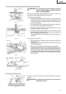
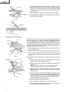
)Slide the miter gauge rearward until the clamped bar is closest
to the tip of the marked saw blade tooth (see Fig. 13-c).
(
11
)If the bar just touched the tooth when the gauge was in the
front position, it should just touch the tooth in the rear position.
Likewise, if there was some clearance between the bar and
the tooth tip at the front, the same clearance should be at the
rear.
(
12
)If the front and rear clearance are not identical,
q Remove the miter gauge.
w Loosen four 6mm flat screws.
e Move the body and adjust it so that a bar placed on the
miter gauge is as wide as the clearance between the front
and rear of the saw blade.
r Tighten the four 6mm flat screws.
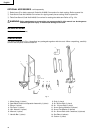
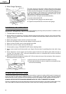
2. Adjusting 90° and 45° positive stops
This tool is equipped with positive stops for rapid and accurate
positioning of the saw blade at 90° and left bevel 45° to the table.
Check and adjust the positive stops by the following procedures.
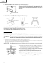
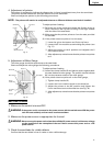
(1) To adjust positive stop at 90°.
q Turn the wheel fully clockwise and set the saw blade to
the maximum cutting height.
w Loosen the saw blade tilt lock handle and move the saw
blade tilting mechanism to the left until it hits against the
stopper.
Then tighten the saw blade tilt lock handle (see Fig. 14-a).
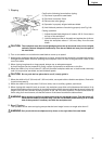
e Use a square to check the saw blade is at a precise 90°
(see Fig. 14-b).
r If the saw blade is not at a precise 90°, loosen the saw
blade tilt lock handle by turning it counterclockwise. Loosen
the 6mm machine screw (A) (see Fig. 13-c) a few turns and
move the saw blade tilting mechanism until the blade is at
90° to the table (see Fig. 14-b).
t Tighten the saw blade tilt lock handle after adjustment.
y Loosen the 5mm machine screw and set the needle pointer
to 0°. On completion of adjustment, recheck the 90° of the
saw blade and table (see Fig. 14-c).
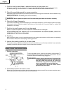
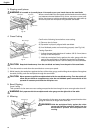
(2) To adjust positive stop at left bevel 45°.
q Turn the wheel fully clockwise and set the saw blade to
the maximum cutting height.
w Loosen the saw blade tilt lock handle and move the saw
blade tilting mechanism to the right until it hits against
the stopper.
Then tighten the saw blade tilt lock handle (see Fig. 15-a).
e Use a 45° gauge to check the saw blade is at a left bevel
45° (see Fig. 15-b).
Fig. 13-b
Bar
Clamp
Handle (B)
Saw Blade
Miter
Gauge
Fig. 13-c
Clamp
Handle (B) Bar
Saw Blade
6 mm Machine
Screw (B)
6 mm Flat
Screw
6 mm Machine
Screw (A)
Miter
Gauge
Fig. 14-a
Fig. 14-c
Fig. 14-b
Saw Blade
Down
Loosen
Tilt Lock Handle
Tighten
Wheel
Up
5 mm Machine Screw
Square
Saw Blade
Needle Pointer