


307-735 17
DISPLACEMENT PUMP
Reassembly Procedure
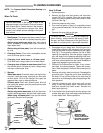
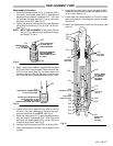
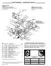
1. Stack the backup washer (219*), U–cup seal (205*)
lips down
, and female gland (220*), alternate the
polyethylene
and leather v–packings (217*, 218*)
lips
up,
and stack
the male gland (213*) one at a time onto
the
piston valve (224).
See Fig 15.
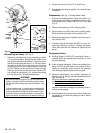
2. Tighten
the packing retaining nut (214) onto the piston
valve
(224) and torque
to 3–4 in–lb (0.34 – 0.35 N.m).
See
Fig 13.
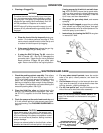
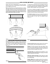
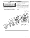
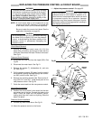
NOTE: NOTE THE ALIGNMENT of the piston (224) to
the nut (214). Maintain this alignment through-
out
Steps 2, 3 and 4.
NOTE
AND MAINT
AIN
THIS ALIGNMENT
THROUGHOUT STEPS
3,4, AND 5
Fig
13
TORQUE
NUT T
O
3–4 IN-LB
(0.34–0.35 N.M)
APPLY ONE DROP
OF SEALANT T
O
THESE THREADS
203*
224
214
3. Apply
1 drop only
of sealant, supplied with the repair
kit, to the piston valve threads. Place the small ball
(203*) on the valve. See Fig 13. Hand tighten the
valve
into
the rod (223) just until the nut contacts the
rod. Place the flats of the displacement rod in a vise.
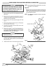
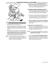
Fig
14
214
TORQUE
NUT AGAINST ROD
T
O 19 FT
-LB (25 N.M)
223
DO NOT ALLOW THIS NUT T
O
MOVE RELA
TIVE T
O THE
PIST
ON (224) WHEN
INST
ALLING PIST
ON ONTO ROD
4. Torque
the nut (214) against the rod (223) to 19 ft–lb
(25 N.m). Use two wrenches to maintain the align-
ment
as mentioned in the
NOTE.
See Fig 14.
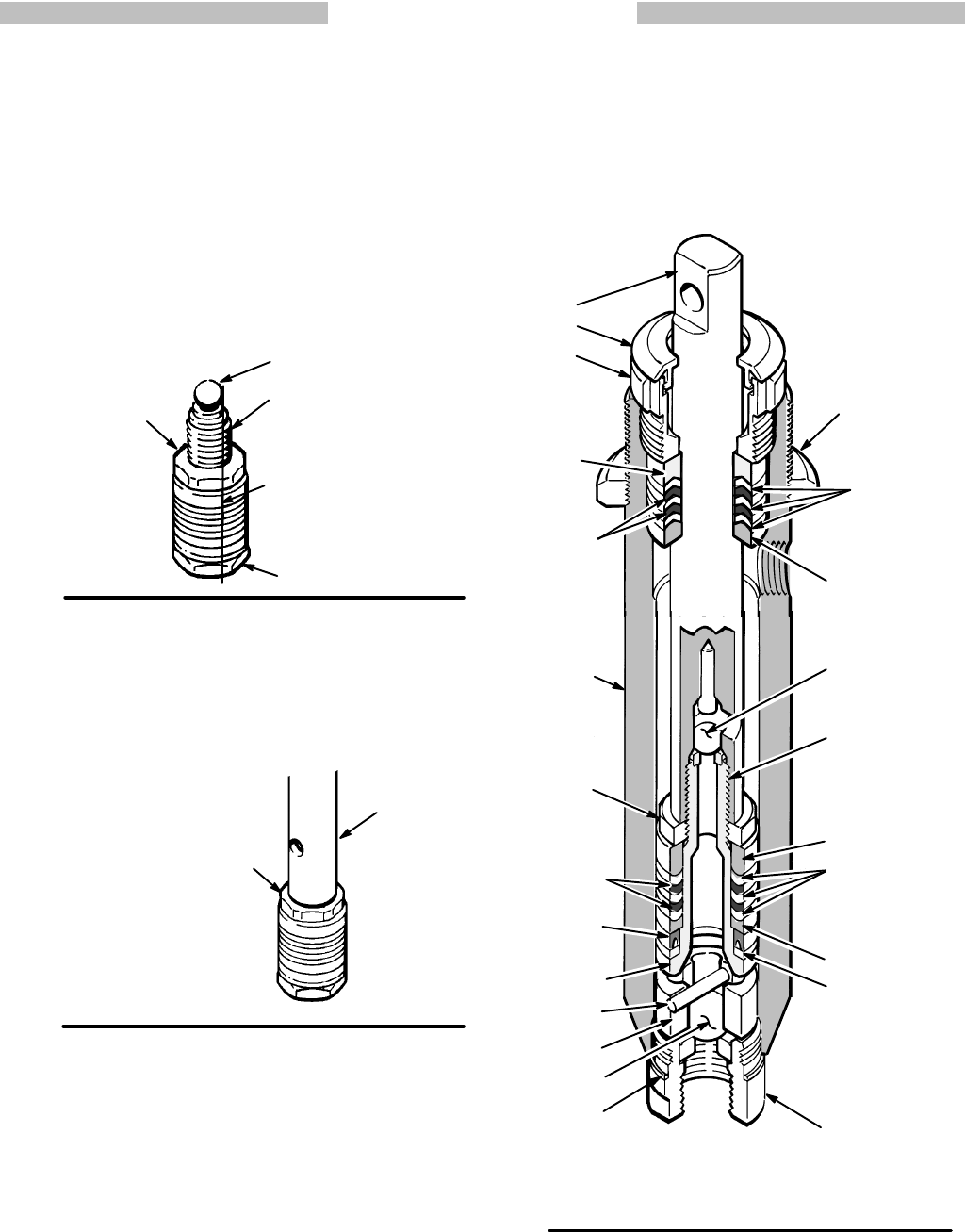
5. Stack the male gland (211*), alternate the
polyethyl
-
ene and leather v–packings (218*, 209*)
lips down
and stack the female gland (212*) one at a time into
the
top of the cylinder
.
See Fig 15.
6.
Loosely install the packing nut (221) and plug (201).
7. Insert
the
oiled piston rod (223) into the bottom of the
cylinder.
8.
Assemble the intake valve. Use a new gasket (206*).
Screw
the valve into the cylinder
and tighten to 80 ft–
lb
(107 N.m).
See Fig 15.
9. Screw
down the cylinder locknut (1
12) until it is finger
tight at the bottom of the external cylinder threads.
See
Fig 15.
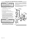
10. Install the displacement pump on the sprayer. See
page
16.
Lips
must face up
*208
216
APPL
Y 1 DROP
OF ADHESIVE
(in repair kit)
T
O THESE
THREADS
Fig
15
201
223
*204
215
222
*206
*207
Lips
must
face up
217*
Lips must
face down
218*
Lips must
face down
*209
224
Lips of seal
must face down
*205
203*
213*
220*
211*
*212
219*
TORQUE TO
80 ft–lb
(107 N.m)
221
112
214