


307-735
20
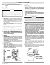
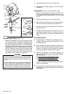
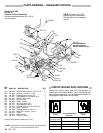
REPLACING THE ELECTRIC MOT
OR & CAP
ACITOR
WARNING
To
reduce the risk of serious bodily injury
,
including
fluid
injection or splashing in the eyes or on the skin,
or
injury from moving
parts, always follow the
Pres-
sure Relief Procedure Warning on page 14 be-
fore
checking, adjusting, cleaning or shutting of
f
the
sprayer.
Unplug the power supply cord.
1. Disconnect
the hose (52) at the displacement pump.
See
Fig 12.
2. Remove
the drive assembly as described on page 19.
The pump, connecting rod and bearing can stay as-
sembled
to the drive assembly
.
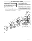
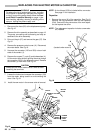
3. Drive
out the pin (27) and remove the gear (37).
See
Fig
18.
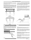
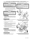
4. Remove
the pressure control cover (41).
Disconnect
the
motor leads.
See Fig 19.
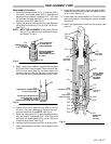
5. Unscrew the connector (130 and 303) nuts on both
ends
of the conduit (1).
6. Remove
the screws (7), nuts (3) and lockwashers (4).
Lift
the motor while carefully guiding the wires through
the
connector (303) in the pressure control. Remove
the
conduit (1) from wires.
See Fig 19.
CAUTION
Always pull the motor leads one at a time to avoid
loosening
the terminals.
7. Loosen
the locknut and unscrew the connector (130)
from the motor, being careful to avoid twisting the
wires.
See Fig 19.
8.
Install the new
motor in the reverse order of removal.
NOTE:
A circuit board (23f) is included
with
a new motor
.
See
page 21 for installation.
Capacitor
1. Remove the cover (A) of the capacitor.
See Fig 18
.
Remove the flag connectors from the old capacitor
(23d).
Connect the flag connectors of the new capaci
-
tor
and replace the cover
.
NOTE: The
replacement capacitor includes a new resis
-
tor,
installed.
Fig 18
27
37
7
23d
23
4
3
(located under cover A)
A
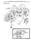
Fig 19
BLACK
GREEN
& YELLOW
RED
PINK
BROWN
WHITE
BLACK
GREEN
POWER
SUPPLY
CORD
LEADS
23c
303
23f
316
130
23
1
133
41
50
301
23a
304
MOTOR
LEADS