


307-735 21
REPLACING THE PRESSURE CONTROL & CIRCUIT BOARD
WARNING
To
reduce the risk of serious bodily injury
,
including
fluid
injection or splashing in the eyes or on the skin,
or
injury from moving
parts, always follow the
Pres-
sure Relief Procedure Warning on page 14 be-
fore
checking, adjusting, cleaning or shutting of
f
the
sprayer.
Unplug the power supply cord.
NOTE: A circuit board (23f) is not included with a new
pressure
control (50). However
, it is included
with
a
new motor
, and it can be ordered separately
.
Be
sure to order the correct circuit board. See
the
application
information on page 24.
CAUTION
Do
not allow the fittings
(A) to move when removing
the elbow (312) or nipple (313) from the pressure
control, to avoid altering the factory setting of the
pressure control or permanently damaging the
pressure
control.
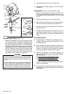
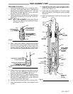
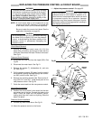
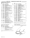
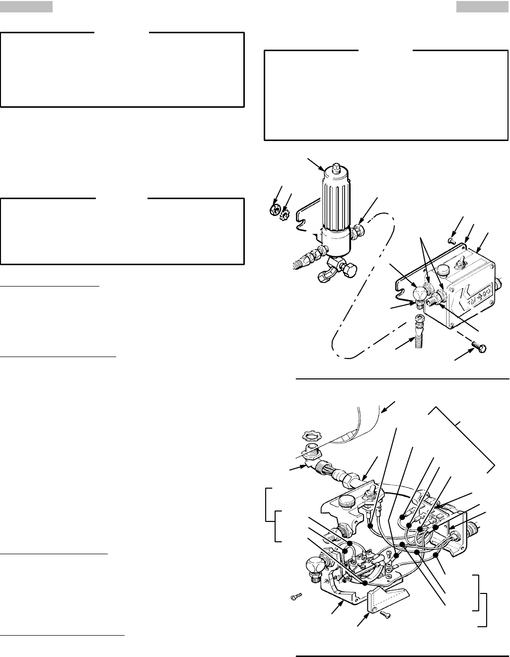
Circuit Board Removal
1. Remove the pressure control cover (41). Pull the
board
(23f) out carefully
, just enough to reach the wire
terminals. Disconnect the leads. Remove the
board.
See Fig 21.
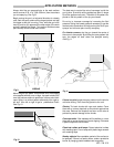
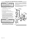
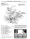
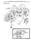
Pressure Control Removal
2. Disconnect the hose (52) from the nipple (302).
See
Fig 20.
3.
Disconnect the motor leads.
See Fig 21.
4. Remove the screws (7), lockwashers (4), and nuts
(3).
See Fig 20
.
5. Pull the pressure control (50) away from the conduit
while
carefully guiding the leads through the connec
-
tor
(303 ) one at a time.
See Fig 21.
6. Remove the mounting bracket (40). Remvoe the fit-
tings (302, 312, and 313). Install these parts on the
new
pressure control.
See Fig 20.
7. Guide
the motor leads into the new pressure control.
Circuit
Board Installation
8. Position the circuit board in the control so the wire
connectors are at the top. Connect the leads to the
board. Guide the leads into the pressure control,
making sure they don’t catch on anything. Slide the
board
into place.
Pressure Control Installation
9.
Connect any other loose wires.
See Fig 21.
10.
Mount the pressure control on the frame.
11.
Adjust the pressure control.
See page 22.
Adjust
the pressure control whenever a new or used
pressure control or circuit board is installed, to re-
duce
the risk of overpressurization which can result
in component rupture, fire or explosion. Improper
adjustment may also prevent the sprayer from ob-
taining
the maximum working pressure, resulting in
poor
sprayer performance.
WARNING
Fig 20
50
7
52
302
4
3
313
A
47
312
84
25
40
Fig 21
23c
303
23f
130
23
41
50
RED
WHITE
WHITE
TRIAC
LEADS
BLACK
GREEN
&
YELLOW
RED
PINK
BROWN
BLACK
POWER SUPPL
Y
CORD LEADS
MOTOR
LEADS
1
WHITE
GREEN