


307-735
22
PRESSURE
CONTROL ADJUSTMENT
USE EXTREME CAUTION WHEN PERFORMING THIS ADJUSTMENT PROCEDURE to reduce the risk of a
fluid injection injury or other serious bodily injury, which can result from component rupture, electric shock, fire,
explosion
or moving parts.
This
procedure sets the sprayer to 2750 psi (190 bar)
MAXIMUM
WORKING PRESSURE.
Perform this procedure whenever the microswitch or
pressure control assembly is reinstalled or replaced,
to
be sure the sprayer is properly calibrated.
Improper adjustment can cause the sprayer to over–
pressurize
and result in component rupture, fire or ex
-
plosion.
It may also prevent the sprayer from obtaining
the maximum working pressure, resulting in poor
sprayer
performance.
NEVER attempt to increase the fluid outlet pressure
by performing these adjustments in any other way.
Normal operation of the sprayer at higher pressures
could
result in component rupture, fire or explosion. T
o
perform this adjustment, however, the sprayer pres-
sure
must be
temporarily
increased
above the normal
working
pressure.
Use a
new
50 foot (15.2 m) spray hose, rated for at
least 3000 PSI (210 BAR) MAXIMUM WORKING
PRESSURE, when performing this procedure. A
used, under–rated hose could develop a high pres-
sure
leak or rupture.
WARNING
Service T
ools Needed:
D NEW
50 foot (15.2 m), 3000
psi (231 bar). flexible ny
-
lon,
airless spray hose, Part No. 223–541
D 0–5000 psi (0–350 bar) fluid–filled pressure gauge,
Part
No. 102–814
D
Needle valve, Part No. 102–715 or 103–067
D
3/8 in. socket wrench
D
5 gallon pail and water
D
Mineral spirits
1. Follow the
Pressure Relief Procedure W
arning
on
page 14.
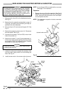
2. Connect the new 50 ft (15.2 m) spray hose to the
sprayer outlet. Install the needle valve on the other
end
of the hose.
Install the fluid–filled pressure gauge
in
the top port of the fluid filter
.
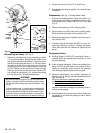
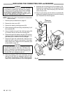
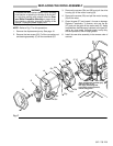
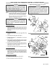
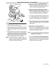
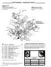
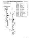
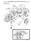
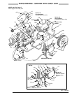
3. Remove
the pressure control
cover (41) and the plug
(135)
(
see the
parts drawings)
from the bottom of the
pressure control. In Step 6, you will insert the 3/8 in.
socket wrench through the plug hole (C) to engage
the pressure adjustment nut (B) which is located on
the
bottom of the pressure control knob shaft.