


12
Chapter 4 WIRING AND CONNECTION
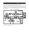
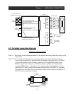
4.3 Terminal connection diagram
Figure 4-2 Terminal wiring
(Note 1) : Please refer to the instruction manual of the inverter main body about the wiring of the
logic board.
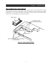
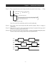
(Note 2) : Use a twisted and shielded wire for the signal cables, and cut the shielded covering as
shown in the diagram below. Make sure that the length of the signal cable is 20 meters
or less. If the length exceeds 20 meters, please use a VX application control device
RCD-E (remote control device) or CVD-E (insulation signal) to avoid malfunction
caused by EMC noise or voltage drop. Also, electric wire for the encoder uses twist
shield line of 0.75mm
2
or more (the example: Hitachi Cable, Ltd. KPEV-S), and make
the distance less than 20m. In case of more than 20m, please use the relay amplifier of
the 5V line driver specification output.
Insulate
Unnecessary ground
connection
Connect to each common terminal
of the o
p
tion board
.
H
O
L
SJ-FB
(Feed-back board)
Inverter main body control terminal
Programmable to the
intelligent input terminal 1-8
EP5
EG5
EAP
EAN
EBP
EBN
EZP
EZN
M
EC
Motor with
the encoder
SAP
SAN
SBP
SBN
Pulse line position
command
POK (Positioning completion signal)
ZS (Zero speed signal)
DSE (Speed deviation excessive signal)
Output
terminal
FW
RV
LAC (LAD cancellation signal)
PCLR (Position deviation Clear signal)
ORT (Orientation signal)
CM1
Input
terminal
Programmable to the
intelligent output terminal 1-5
AP
AN
BP
BN
Encoder
signal output
STAT(Pulse train input permission signal)
Encoder signal
TM1
TM2