


25
Chapter 7 FUNCTIONS
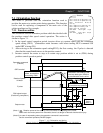
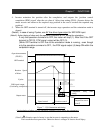
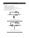
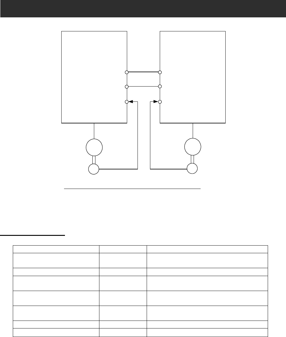
Figure 7-3 Wiring for Synchronized Operation
(Note) : Please connect EG5 of the main and sub inverter together to avoid
malfunction caused by EMC noise.
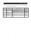
7.3.3 Data setting
Data setting related to position control
Setting item Function code Setting range, setting contents
Feed-forward gain
(Note 1)
P022
0.00∼99.99 / 100.0∼655.3
Position loop gain (Note 2) P023
0.00∼9.99 / 100.0 (rad/s)
Electronic gear position
selection(Note 3)
P019
00: to the feed back side (FB)
01: to the position command side (REF)
Numerator of the electronic gear
ratio (Note 3)
P020
1∼9999
Denominator of the electronic
gear ratio (Note 3)
P021
1∼9999
Completion range setting P017
0∼9999. / 1000 (10,000) (pulse)
Completion delay time P018
0.00∼9.99 (s)
(Note 1) : We promote the adjustment from P022=2.00 at the time of the feed forward gain
adjustment .To make the position deviation of the main and sub motor small, then
increase feed forward gain. When the motor is unstable, then decrease feed forward gain
(Note 2) :We promote the adjustment from P023=2.00 at the time of the position loop gain
adjustment. To get good accuracy of the position control then increase posotion loop gain,
then to get much power to maintain the positioning then increase posotion loop gain.
Motor is unstable due to too big position loop gain, then decrease position loop gain.
Master Inverter Slave Inverter
AP,BP
AN,BN
SAP,SBP
SAN,SBN
EG5
EAP,EBP
EAN,EBN
EG5
EAP,EBP
EAN,EBN
M
EC
M
EC
Main Motor
Sub Motor