


12 OM-185 158
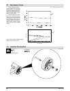
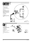
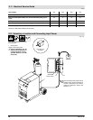
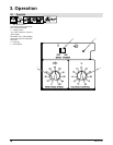
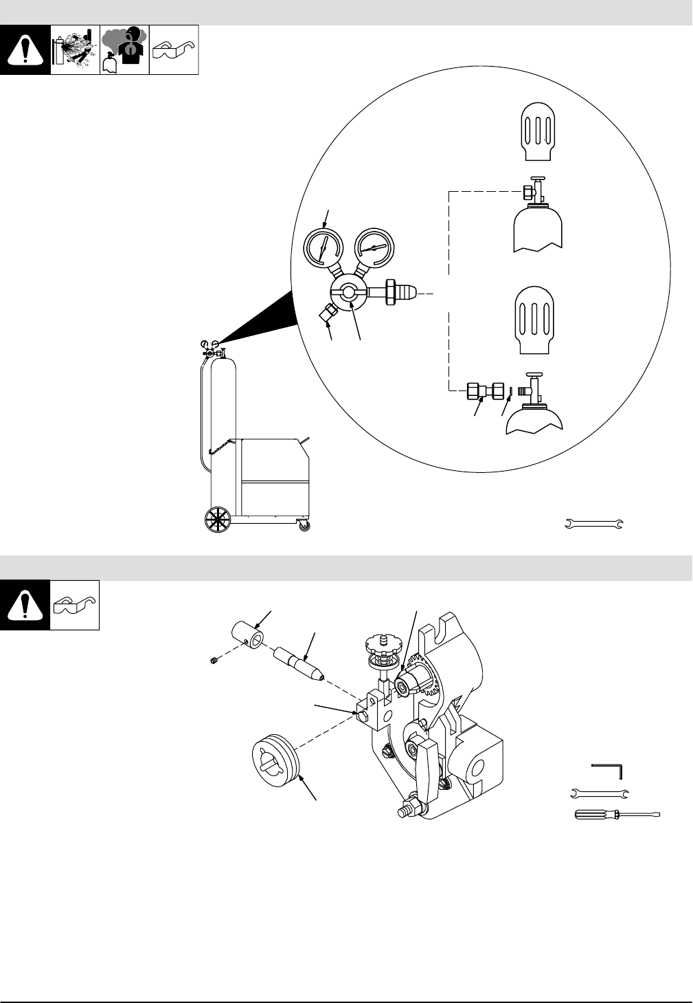
2.7 Installing Gas Supply
Ref. ST-801 789 / Ref. ST-149 827-B / Ref. ST-158 697-A
1
Tools Needed:
2
CO
2
Gas
4 5
1
Argon Gas
OR
3
Chain gas cylinder to running gear,
wall, or other stationary support so
cylinder cannot fall and break off
valve.
1 Regulator/Flow Gauge
Install so face is vertical.
2 Gas Hose Connection
Fitting has 5/8-18 right-hand
threads.
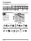
3 Flow Adjust
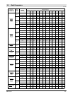
Typical flow rate is 20 cfh (cubic
feet per hour). Check wire man-
ufacturer’s recommended flow
rate (see Section 3.2). This flow
gauge can be adjusted between 5
and 25 cfh.
4CO
2
Adapter
Customer Supplied
5 O-Ring
Install adapter with O-ring between
regulator/flow gauge and CO
2
cylinder.
1-1/8, 5/8 in
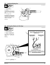
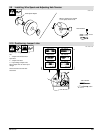
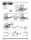
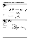
2.8 Installing Drive Roll and Wire Inlet Guide
ST-150 227-C
Tools Needed:
1
3
2
4
5
1 Securing Screw
2 Inlet Wire Guide
Loosen screw. Slide tip as close to
drive rolls as possible without touch-
ing. Tighten screw.
3 Anti-Wear Guide
Install guide as shown.
4 Drive Roll
Install correct drive roll for wire size
and type.
5 Drive Roll Securing Nut
Turn nut one click to secure drive
roll.
5/64 in
7/16 in