


19
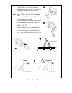
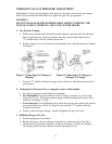
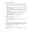
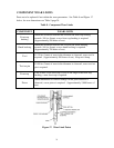
4. Main Valve Box Assembly
Service of the Valve Box includes the Mode Valve Assembly and the Main Valve
with Box Sleeve.
a. Remove six or eight (depending on hammer model) Valve Box (4) Set Bolts and
place Valve Box on a clean flat service.
Note: Inspect o-rings located at ports on cylinder and replace o-rings as
necessary. When re-installing Valve Box check that all o-rings are
in correct position.
b. Remove four Mode Valve (1) Set Bolts and replace o-ring seals as necessary.
c. Remove ten socket head cap screws and the Upper Valve Cap (3) and Lower
Valve Cap (7).
d. Remove the Box Sleeve (6) and the Main Valve (5) from the Lower Valve bore
and inspect for scoring or wear.
Note: Minor scratches can be polished by hand using the same procedure
as the piston and cylinders. Ref. Para. 6 page 27. Main Valve (5)
and Box Sleeve (6) must be capable of free movement by hand
without sticking or dragging. If not satisfactory replace with new
parts.
e. Reassemble by reversing above procedure.
Note: Keep work area clean and lubricate all parts with clean hydraulic
oil during assembly.
f. Torque bolts to proper specifications and sequence shown on Table 4 and figure 5
on page 14.
Figure 13. Main Valve Box Assembly