


VGM, VGD-0505
8
Refrigeration
THERMOSTATIC EXPANSION VALVE LOCATION
This device is located on the same side as the refrigera-
tion stub. An ALCO expansion valve model is furnished
as standard equipment, unless otherwise specified by
customer.
EXPANSION VALVE ADJUSTMENT
There is one (1) valve on the right side of each coil.
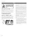
MEASURING THE OPERATING SUPERHEAT
1. Determine the suction pressure with an accurate
pressure gauge at the evaporator outlet.
2. From a refrigerant pressure temperature chart, de-
termine the saturation temperature at the observed
suction pressure.
3. Measure the temperature of the suction gas at the
thermostatic remote bulb location.
4. Subtract the saturation temperature obtained in step
No. 2 from the temperature measured in step No. 3.
5. The difference is superheat.
6. Set the superheat for 5°F - 7°F.
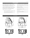
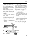
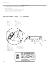
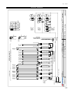
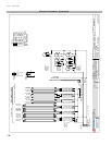
T-STAT LOCATION
T-Stats are located within the electrical raceway. Refer to
diagram below.
CASE FRONT
DRAIN
MECHANICAL
STUB UP AREA
19" X 19"
CASE FRONT
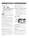
T-STAT AND BALLAST LOCATIONS
WATER,
ELEC. &
REFRIG.
MECHANICAL
STUB UP AREA
19" X 19"
DRAIN
C
L
B
T
B
SELF CONTAINED CASES
The only difference between a remote case and a self-
contained case is the addition of a condensing unit.
SELF CONTAINED START-UP
Self contained cases are totally ready to run once power
is supplied. All controls are set and units charged with
refrigerant.
DEFROST SET-UP
Defrost times vary according to case model - refer to
Case specification section in the back of the book for
proper duration and frequency. Self contained cases have
individual defrost time clocks. When power has been
applied, set the time clock to the proper duration and
frequency.
The time clock is located behind the front panel under
the case. Turn the clock dial counterclockwise until the
pointer is directed to the current time of day.
REFRIGERANT TYPE
The standard refrigerant will be R-22 unless otherwise
specified on the customer order. Check the serial plate
on the case for information.
REFRIGERATION LINES
LIQUID SUCTION
3/8" O.D. 5/8" O.D.
NOTE: The standard coil is piped at 5/8" (suction); however, the
store tie-in may vary depending on the number of coils
and the draw the case has. Depending on the case setup,
the connecting point in the store may be
5
/
8
",
7
/
8
", or 1
1
/
8
". Refer to the particular case you are
hooking up.
Refrigerant lines should be sized as shown on the
refrigeration legend furnished by the store.
Install P-traps (oil traps) at the base of all suction line
vertical risers.
Pressure drop can rob the system of capacity. To keep the
pressure drop to a minimum, keep refrigerant line run as
short as possible, using the minimum number of elbows.
Where elbows are required, use long radius elbows only.
CONTROL SETTINGS
See the “Case Specs” section of this guidebook for the
appropriate settings for your merchandiser. Maintain
these parameters to achieve near constant product
temperatures. Product temperature should be measured
first thing in the morning, after having been refrigerated
overnight. For all multiplexing, defrost should be time
terminated. Defrost times should as directed in the
Case Specifications section of this guide. The number of
defrosts per day should never change. The duration of
the defrost cycle may be adjusted to meet conditions
present at your location.
ACCESS TO TX VALVES & DRAIN LINES
MECHANICAL - Remove product from end of case.
Remove product racks. Remove refrigeration and drain
access panels (labeled). TX valve (mechanical only) and
drain are located under each access panel at end of the
case.
ELECTRONIC - The Electronic Expansion valve master
and slave cylinder(s) are located within the electrical
access panel(s).
ELECTRONIC EXPANSION VALVE
(OPTIONAL)
A wide variety of electronic expansion valves and case
controllers can be utilized. Please refer to EEV and
controller Hussmanns information sheet. Sensors for
electronic expansion valves will be installed on the coil
inlet, coil outlet, and in the discharge air. (Some super-
markets require a 4th sensor in the return air). Case
controllers will be located in the electrical raceway or
under the case