


Page 14
Testing the Voltage Function (for 61-340 / 61-342)
To verify accuracy in the AC and DC voltage ranges, do the following:
1. Turn the rotary switch to “
” position.
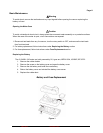
2. Connect the calibrator to the
and COM inputs on the meter.
3. Set the calibrator for the voltage from step 1 to 7 in Table 1.
4. Compare the reading on the meter display with the display reading shown in Table 1.
5. If the display reading falls outside of the range shown in Table 1, the meter does not meet
specification.
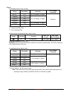
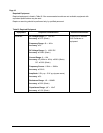
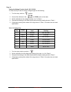
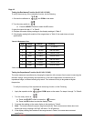
Table 1 DC Voltage Test:
Step
Range
Input Reading
1
400mV
-300.0mV -297.3 to -302.7
2
400mV
4.0mV 3.6 to 4.4
3
400mV
300.0mV 297.3 to 302.7
4
4V
3.000V 2.975 to 3.025
5
40V
30.00V
29.75 to 30.25
6
400V
300.0V
297.5 to 302.5
7
1000V
1000V
987 to 1013
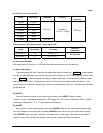
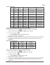
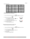
1. Turn the rotary switch to position. “
”
2. Set the calibration for the voltage and frequency from step 1 to 10 in Table 2.
3. Compare the reading on the meter display with the display reading shown in Table 2.
4. If the display reading falls outside of the range shown in Table 2, the meter does not meet
specification.
Form Number 2 TM61340-2 Rev November 2007