


Page 18
Testing the Resistance Function (for 61-340 / 61-342)
To verify the accuracy of the resistance function, do the following:
1. Connect the calibrator to
and COM on the meter.
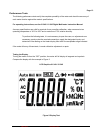
2. Turn the rotary switch to
.
a. Press the SELECT button to select the Ω function
3. Apply the inputs for step 1-7 in Table 5.
4. Compare the meter display readings to the display readings in Table 5.
5. If the display reading falls outside of the range shown in Table 5, the meter does not meet
specification.
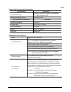
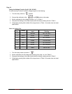
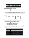
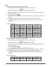
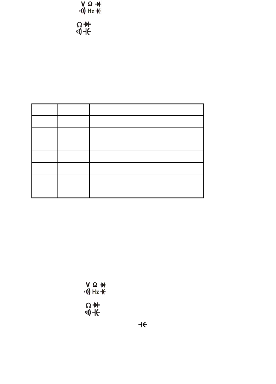
Table 5 Ω Resistance Test:
Step
Range
Source Reading
1
400Ω*
4.0Ω 3.5 to 4.5
2
400Ω*
300.0Ω 295.9 to 304.1
3
4kΩ
3.000KΩ 2.968 to 3.032
4
40kΩ
30.00KΩ 29.68 to 30.32
5
400kΩ
300.0KΩ 296.8 to 303.2
6
4MΩ
3.000MΩ 2.968 to 3.032
7
40MΩ
30.00MΩ 29.35 to 30.65
*Lead resistance on the 400Ω range is not included in error.
Testing the Capacitance Function (for 61-340 / 61-342)
The meter measures capacitance by charging the capacitor with a known direct current, measuring the
resultant voltage, and calculating the capacitance. If the same capacitance is measured on an
impedance bridge, a different reading may result. This variance is likely to be greater at higher
frequencies.
To verify the accuracy of the capacitance measuring function, do the Following:
1. Apply the capacitor to the
and COM inputs on the meter. For steps 1 through 7 in Table 6.
2. Turn the rotary switch to
.
a. Press the SELECT button to select the
function
b. Press the REL button to make the display is zero
3. Compare the reading on the meter display to the reading in Table 6.
4. Note : The meter selects the proper range automatically. Each measurement takes about one
second per range, readings >40.00μF will take ≥ 5 to 30 seconds
Form Number 2
5. If the display reading falls outside of the range shown in Table 6, the meter does not meet
specification.
TM61340-2 Rev November 2007