


Page 19
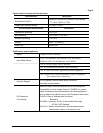
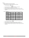
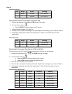
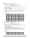
Table 6 Capacitance Test:
Step
Range
Source Reading
1
40nF
10.000nF 9.60 to 10.40
2
40nF
30.00nF 29.00 to 31.00
3
400nF
300.0nF 290.5 to 309.5
4 4µF 3.000µF 2.905 to 3.095
5 40.00µF 30.00µF 29.05 to 30.95
6 100.0µF 100.0µF 79.5 to 120.5
7 1000µF 1000µF 795 to 1205
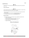
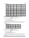
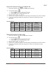
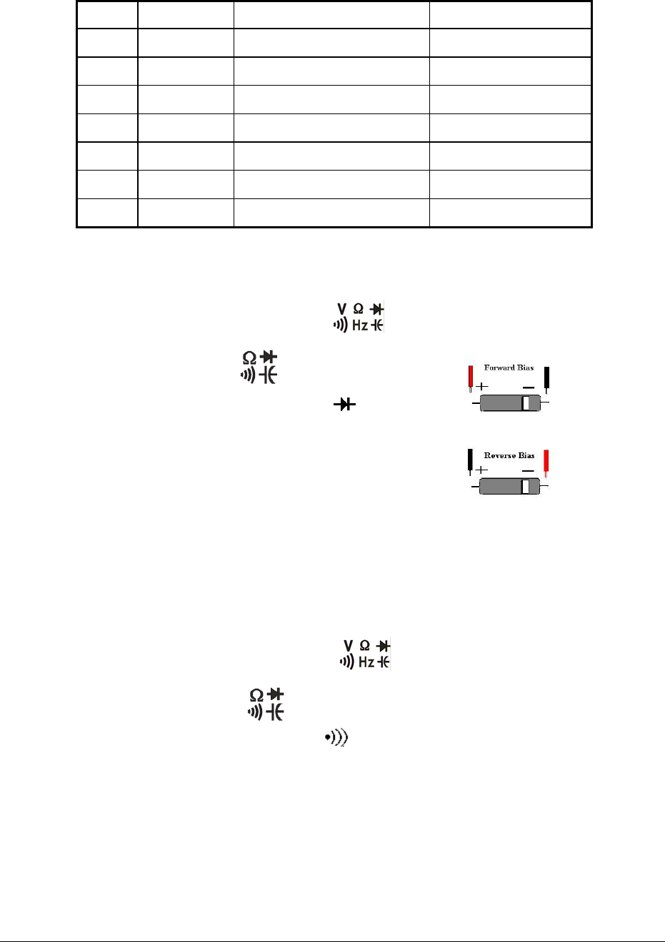
Checking the Diode Test Function (for 61-340 / 61-342)
To check the diode test function, do the following:
1. Connect the DVM (Digital Voltage Meter) to the
and COM inputs on the meter.
2. Turn the meter’s rotary switch to
.
Press the SELECT button to select the function
The DVM display should display OL
3. Insert a Si diode with correct polarity “+” and “-“
The meter display should read within 0.5~0.7Vdc
4. Reverse polarity on the Si diode
The meter display should read OL
.
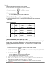
Checking the Continuity Function (for 61-340 / 61-342)
To check the diode test function, do the following:
1. Connect the DVM (Digital Voltage Meter) to the
and COM inputs on the meter.
2. Turn the meter’s rotary switch to
.
a) Press the SELECT button to select the
function
b) The DVM display should display OL
3. Insert a 50Ω resistor
a) The meter inner beeper will sound
Form Number 2 TM61340-2 Rev November 2007