


Page 15
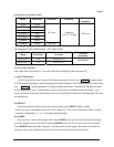
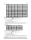
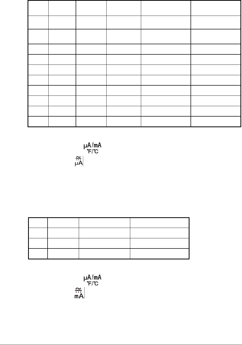
Table 2 AC Voltage Test:
Step Range Input Frequency Reading 61-340 Reading 61-342
1 400mV 300mV 60 295.6 to304.4 295.6 to304.4
2 400mV 300mV 400 295.6 to304.4 295.6 to304.4
3
4V
3.000V 60Hz 2.965 to 3.035 2.965 to 3.035
4
4V
3.000V 400Hz 2.965 to 3.035 2.965 to 3.035
5
40V
30.00V 60Hz 29.65 to 30.35 29.65 to 30.35
6
40V
30.00V 400Hz 29.65 to 30.35 29.65 to 30.35
7
400V
300.0V 60Hz 296.5 to 303.5 296.5 to 303.5
8
400V
300.0V 400Hz 296.5 to 303.5 296.5 to 303.5
9
750V
750V 60Hz 736 to 764 736 to 764
10
750V
750V 400Hz 736 to 764 736 to 764
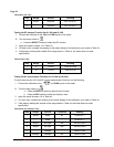
Testing the DC microamperes Function (for 61-340 and 61-342)
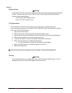
To verify the accuracy of AC and DC current measurement functions, do the following:
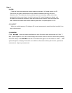
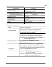
1. Connect the calibrator to the
and COM inputs on the meter.
2. Turn the rotary switch to
a. Press the SELECT button to select the DC function
3. Apply the inputs for steps 1-3 in Table 3a.
4. For each input, compare the reading on the meter display to the reading for your meter in Table 3a
5. If the display reading falls outside of the range shown in Table 3a, the meter does not meet
specification.
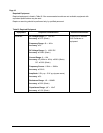
Table 3a DC microamperes Test:
Step
Range
Source Reading
1
400µA
4.0µA 3.5 to 4.5
2
400µA
300.0µA 297.4 to 302.6
3
4000µA
3000µA 2974 to 3026
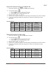
Testing the DC milli amperes Function (for 61-340 and 61-342)
1. Connect the calibrator to the
and COM inputs on the meter.
2. Turn the rotary switch to
.
a. Press the SEL button to select the DC function
3. Apply the inputs for steps 1-4 in Table 3b.
4. For each input, compare the reading on the meter display to the reading for your meter in Table 3b
5. If the display reading falls outside of the range shown in Table 3b, the meter does not meet
specification.
Form Number 2 TM61340-2 Rev November 2007