


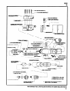
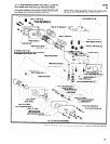
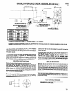
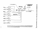

DOUBLE HYDRAULIC CHECK ASSEMBLIES 46133-( )
46132 BRACKET
Y99-43 CAP SCREW (2)
HYDRAULlC
CHECK
CHECK
HYDRAULlC HYDRAULIC
ASSEMBLY NO.
"A"
CHECK "B"
46133-11
38922
38922
46133-12
38922
38922-1
46133-13
30922 38922-2
46133-22
38922-1
30922-1
46133-23
38922-1
38922-2
I
38133-33 38922-2 38922-2
I
HYDRAULIC CHECK NO. 38922 = 1”
STROKE, 38922-1 = 2” STROKE.
46133-11
Ml05
40
AS-
The dual hydraulic check assembly (46133- ) is an accessory
item used to replace the standard hydraulic check when addition-
al thrust control during the drilling operation and/or at break-
through is required.
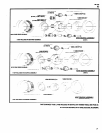
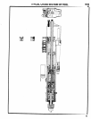
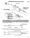
screw (Y157-64) from the trip bracket for use with the new trip
bracket (46132).
The dual system can be used when two different thrust control re-
quirements are needed - for example, a 2” stroke length check
and a 1” stroke length check. When used together, the 2” stroke
length check controls the initial part of the drilling operation and
the 1” stroke is set to give additional control at breakthrough.
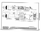
Assemble adapter plate (48131) to trip bracket (46132) and se-
cure with the two 1/4”- 20 x 1/2” long cap screws (Y94-40) and
two washers (30997). Assemble the two clamping screws
(Y9942) with washers (30997) and the adjusting screw
(Y157-64) to trip bracket and assemble the trip bracket to tool.
Position trip bracket on piston rod for desired stroke and tighten
the two screws (Y99-42), securing trip bracket on piston rod.
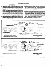
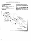
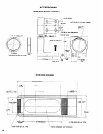
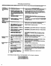
MOUNTING INSTRUCTIONS
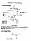
SET-UP PROCEDURE
Remove hydraulic check assembly supplied with tool.
Determine which of the three mounting positions on housing is
best suited for the operation to be performed and assemble
mounting bracket (46130) to housing using the three 1/4”- 20 x
5/8” long cap screws (Y99-458) and tighten securely. Insert hy-
draulic checks thru mounting bracket, positioning for desired
stroke and secure with the two 1/4”-20 x 1-114” long cap screws
(Y99-43) and two washers (30997).
Basically, the set-up procedure for the dual hydraulic checks is
the same as for the single hydraulic check, except you will be do-
ing each step of the set-up twice. After the stroke length set-up is
made, synchronize the two checks more or less by rotating the
feed rate adjustment of each check to approximately the same
number. This is when two checks of the same stroke lengths are
being used to control thrust.
Remove trip bracket (44909) from tool and remove the two clamp-
When using two checks of different stroke lengths, testing set-up
ing screws (Y99-42) and washers (30997) and the adjusting
on a few scrap work pieces will be the best way in determining
proper rates of feed.
.
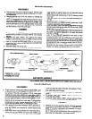
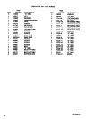
46253 SPANNER WRENCH
FOR REMOVAL OF 45159 BEARING LOCK SCREW,
AVAILABLE AT EXTRA COST.
13