


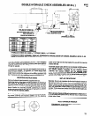

top of valve housing. The unit will immediately retract to the initial
position, whereupon the unit will stop with all air to the unit shut off.
The needle type retract feed control valve regulates the flow of air
from the piston, thus regulating the rate of retraction of the unit.
The model 8670-( ) is furnished with a hydraulic check to control
the rate of forward feed of the unit-see page 12 for set-up proce-
dure.
SPECIAL NOTE: There are two needle valves (34617) contained
in the valve block. One needle valve is for the retract feed control.
The other needle valve [visible only after the removal of the name-
plate (45184)) should not be adjusted or removed. If this needle
valve should ever be removed, the correct assembled position is
-the top of the needle valve flush with the top of the valve block.
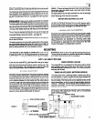
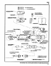
The unit may be operated remotely thru the use of the start and
retract signal ports located in top of the valve housing, using rec-
ommended fittings, tubing and valves - see page 16.
The auxiliary supply port is pressurized whenever air is present at
the air inlet of the tool.
The depth signal port is momentarily pressurized at the comple-
tion of the forward feed stroke when the retract valve (44981) is
actuated and can be used to activate a remote valve for the pur-
pose of starting another tool or an accessory function.
M105
40
The tool retracted signal port is located in rear of piston rod
(44928-). The port is pressurized when motor starts and remains
pressurized during the drilling cycle, until motor shuts off when
unit is fully retracted.
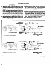
The valve section can be easily removed from tool for servicing
and replaced with a spare unit, eliminating excessive down-time
of tool. See page 4 for removal instructions.
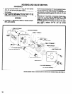
MOTOR AND GEARING SECTION
The motor and gearing section has been designed into a single
unit that can be easily removed from tool and replaced with a
spare unit while it is being serviced or repaired, eliminating exces-
sive down-time of tool. See page 4 for removal from tool.
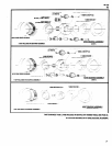
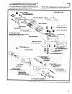
HOUSING AND VALVE SECTION
The housing and valve section consists of a main housing, which
houses the piston section and motor and gearing section, and the
valve housing, which houses the retract valve that is actuated by
the adjustment screw contained in the trip bracket. The retract
valve components are accessible by removing striker plate
(44987) from rear of valve housing. The piston and components
are accessible by separating the main housing from the
valve
housing. See page 4 for disassembly procedure.
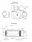
MOUNTING
The nose end of tool housing is provided with 2-7/8”-16 I.h.
as accessory items for tool mounting (see accessories section).
threads and a 2.873” x 2-1/4” long pilot diameter for fixture mount-
The tool can be mounted in any position desired without impairing
ing. A foot type mounting bracket and nose housing are available
the function of the tool (see set-up procedure).
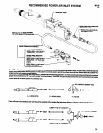
SET-UP PROCEDURE
At the time the model 8670-( ) self-feed drill is set up for opera-
tion, a minimum distance of 1/4” must be maintained between the
work piece and the point of the drill bit, with the drilling unit in the
fully retracted position. This will allow the air motor to start and
reach free speed before the drill reaches the work piece.
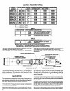
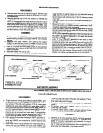
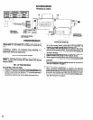
STROKE ADJUSTMENT
Determine the total stroke length the drill must travel to perform
the drilling operation (see figure 1). Adjust the length of the stroke
by loosening the two cap screws (Y99-42) which secure the trip
bracket to the piston rod. Position the trip bracket on the piston rod
so the distance between the trip bracket and the striker plate is
somewhat greater than the desired stroke length and tighten the
two screws (Y99-42), securing trip bracket on piston rod. Next, ro-
tate adjustment screw (Y157-64) so the distance between the
leading edge of the screw and the striker plate equals the desired
total stroke length. A final adjustment of the adjustment screw can
be made while testing the drilling operation on a few scrap work
pieces to insure desired drilling depth is obtained.
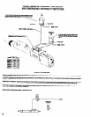
FEED CONTROL VALVES
The models 8670-( ) are shipped from the factory with the retract
feed regulating valve set at a fairly slow rate of feed. Turn valve
counterclockwise to increase rate of feed. Turn valve clockwise to
decrease rate of feed.
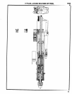
TIMING VALVES (59231 METERING NEEDLE)
The timing valve (59231 metering needle), located at the rear of
the valve section, is used to regulate the time lapse between the
time the drill bit has reached the pm-set drilling depth and the time
the unit retracts. The timing valve can be adjusted so the unit will
retract immediately, up thru a range of approximately seven se-
conds (0 - 7 seconds). Turn the timing valve clockwise (in) to in-
crease the time delay. Turn the valve counterclockwise (out) to
decrease the time delay.
NOTE: A final adjustment of the adjusting screw (Y157-64) may
be necessary after adjusting the timing valve to insure precise
depth of drilling operation.
RETRACT VALVE
ADJUSTMENT SCREW
TOTAL STROKE LENGTH
3