


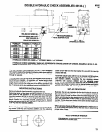

AIR AND LUBE REQUIREMENTS
Air pressure of 90 p.s.i.g. (6 bar) at the air inlet of the tool is re-
quired for maximum motor efficiency. If necessary, an air regulator
should be installed to maintain this pressure when tool is in opera-
tion.
Filtered and oiled air will allow the tool to operate more efficiently
and yield a longer life to operating parts and mechanisms. A line
filter capable of filtering particles larger than 50 microns should be
used with a line oiler.
Inject 33153 grease (3 to 4 strokes) thru grease fitting located at
top of main housing after each 160 hours of operation, or as expe-
rience indicates, for lubrication of gearing and spindle bearings.
NOTE: Be sure tool is in the fully retracted position when injecting
grease thru fitting. CAUTION: An excessive amount of lubricant in
a tool will affect the speed and power.
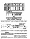
RECOMMENDED HOSE SIZE: 1/2” (13 mm) nominal inside di-
ameter.
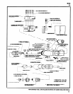
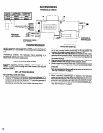
Filter-Regulator-Lubricator (F-R-L) assembly model RECOMMENDED LUBRICANTS: Spindle oil 29665, 1 qt. (.9 liter)
C28241-810 is recommended for use with this air tool. The ca- container for oiler and air inlet; Grease 33153, 5 lb. (2.3 kg) can for
pacity of the individual filter-lubricator is adequate to provide gears and bearings; “0” ring lubricant 36460, 4 oz. (113 g) tube for
clean (40 micron) oiled and regulated air for the tool. lubrication and installation of “0” rings.
MAINTENANCE
Air tools are made of precision parts and should be handled with
reasonable care when servicing. Excessive pressure exerted by
a holding device may cause distortion of a part. Apply pressure
evenly when disassembling (or assembling) parts which have a
press fit. When removing or installing bearings, apply pressure to
the bearing race that will be press fit to the mating part; if this is not
practiced, Brinelling of the bearing races will occur, making re-
placement necessary. It is important that the correct tools and fix-
tures are used when servicing this air tool.
Disassembly should be done on a clean work bench with a clean
cloth spread to prevent the loss of small parts. After disassembly
is completed, all parts should be thoroughly washed in a clean sol-
vent, blown dry with air and inspected for wear levels, abuse and
contamination.
Double sealed or shielded bearings should never be placed in
solvent unless a good method of relubricating the bearing is avail-
able. Open bearings may be washed but should not be allowed to
spin while being blown dry. When replacement parts are neces-
sary, consult drawing containing the part for identification.
Before reassembling, lubricate parts where required. Use 33153
grease, or equivalent, in bearings. Use 36460 lubricant for “0
ring assembly. When assembling “0” rings, care must be exer-
cised to prevent damage to the rubber sealing surfaces. A small
amount of grease will usually hold steel balls and other small parts
in place while assembling.
When ordering parts, be sure to list part number, part name, model
number and serial number of tool. Use only genuine ARO© re-
placement parts.
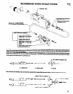
DISASSEMBLY AND ASSEMBLY OF TOOLS
Disconnect air supply from tool or shut off air supply and drain line
of compressed air before performing maintenance or service to
tool.
Before starting to disassemble or assemble this tool (any part or
completely), be sure to read “Maintenance” section.
To minimize the possibility of parts damage and for convenience,
the steps for disassembly or assembly listed on the following
pages are recommended.
The basic sections and instructions for removing them from the
tool are as follows:
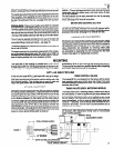
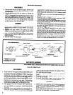
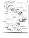
VALVE SECTION
First, disconnect tubing from ports if any is being used. Remove
five screws (Y211-109) with washers (Y14-10), and lift valve
section (45174) off valve housing (44919). For disassembly of
valve section, see page 8.
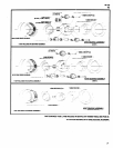
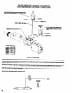
MOTOR AND GEARING SECTION
Loosen four screws (Y211-102) and remove control cover
(44947) off rear of tool. Using a wrench on flats at end of piston rod
(44928-), unthread piston rod from nut (44988) which secures
piston rod to motor and gearing section. Do not attempt to remove
piston rod from housing at this time. The main housing and valve
housing must be separated for removal of rod (see “Housing and
Valve” section). Next, remove screw (Y 154-31) and remove mo-
tor and gearing section from main housing and key (44929-2).
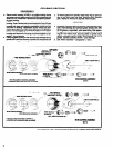
For disassembly of gearing, see pages 6 and 7. For disassembly
of motor, see page 8.
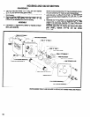
HOUSING AND VALVE SECTION
To remove piston rod (44928- ) and to gain access to piston
(44985), loosen four screws (Y211-1 02) and remove control cov-
er (44947). Loosen two screws (Y99-42) and slip trip bracket
(44909) off end of piston rod. Unthread piston rod (44928-) from
nut (44988) using a wrench on flats at rear end of rod. Main hous-
ing and valve housing must be separated before rod can be re-
moved. Remove four screws (Y99-42) with washers (30997)
and separate valve housing (44919) from main housing (44989).
Use reasonable care when removing valve housing off piston rod
so as not to damage rod or components in valve housing. The re-
tract valve (44981) and components are accessible after remov-
ing control cover, trip bracket, three screws (Y211-102) and
washers (Y14-10) and striker plate (44987). See page 10 for
complete disassembly.
4