


MOTOR SECTION
DISASSEMBLY
a.
Remove motor from tool as outlined on page 4. Remove motor
assembly from housing as outlined in paragraph “a” of gear-
ing disassembly.
b.
Remove retaining ring (Y145-18) retainer nut (45189) and
nut (44980).
NOTE: It is suggested that brass blocks be used in a vise or
some other suitable fixture to clamp on splines of rotor to keep
from turning while removing or tightening nut (44980). Care
must be exercised so as not to damage splines of rotor shaft.
c.
Grasp cylinder in one hand and tap splined end of rotor with a
soft face hammer; motor will come apart.
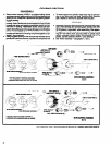
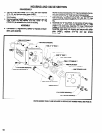
ASSEMBLY
a.
Pack bearings with ARO 33153 grease, or equivalent, and as-
semble bearing (34690) to end plate (44974) with shielded
side out.
b. Assemble end plate (44974), with bearing and spacer
(33555), to rotor and secure with nut (44980). Torque nut to 26
- 30 ft Ibs. Bearings are press fit on rotor.
c.
Coat i.d. of cylinder with ARO 29665 spindle oil and assemble
cylinder over rotor, aligning air inlet and roll pin of cylinder with
holes in end plate.
d. Assemble blades into slots in rotor.
e.
Assemble spring washer (35963) to end plate (44975), with
large diameter of washer facing out, and assemble bearing
(Y65-12) to end plate. Assemble end plate to rotor and cylin-
der and secure with retaining ring (Y145-18). Bearing is press
fit on rotor.
f. Assemble retainer nut (45189) to end plate and torque to 9 -
12 ft Ibs.
g. Be sure rotor does not bind and assemble motor to housing.
NOTE: Be certain nut (44988) is properly positioned in hous-
h.
ing before assembling motor to housing.
Assemble spacer (44994) and gearing assemblies to housing
and secure with bearing lock screw (45159) with seal (37942)
and bearing lock nut (45158).
NOTE: When assembling gearing to motor housing, be sure
key (33017) is properly positioned in ring gear and aligned
i.
with slot in housing.
Lube “0” ring (Y325-227) attached to rear head of motor
housing with ARO 36460 “0” ring lube and assemble motor
and gearing section with key (449292)to main housing and
secure key into housing with screw (Y154-31). NOTE: When
assembling key, be sure hole thru key is properly positioned
j.
and aligned with hole in housing to accept screw (Y154-31).
Thread piston rod into nut (44988) securing motor and gear-
ing section into main housing. Using a wrench on flats at rear
of piston rod, tighten rod securely but do not overtighten.
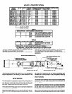
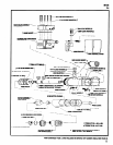
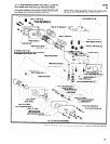
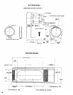
44977 MOTOR ASSEMBLY
PARTS MARKED
THUS Cl ARE
INCLUDED IN SERVICE
KIT NUMBER
45632,
SEE PAGE 20.
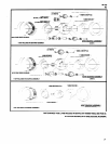
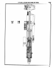
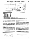
VALVE SECTION
DISASSEMBLY
a.
To gain access to timing valve (metering needle 59231) and/
or reversing valve (actuator 59572) and components, remove
four screws (Y154-38) with washers (Y79-6) cover plate
(44954) and valve body (44953) from valve block (44927).
Use reasonable care when removing cover plate (44954) so
as not to cause damage to metering needle (59231) or com-
ponents. After removal of cover plate, insert (59597) and com-
ponents can be removed from valve body. To disassemble
components from insert, remove retaining ring (Y147-1). Un-
thread metering needle (59231) to remove from insert.
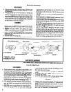
b.
After removal of cover plate, diaphragm (58037) and valve ac-
tuator (59572) can be removed from valve body. To remove
valve seat (44955) and components, remove retaining ring
(Y247-75).
c.
Spool valve (44978) can be removed from valve block after re-
moving the end cap (44949) and cover plate (44954) and
valve body (44953). To remove end cap, remove three screws
8
(Y154-32) and one screw (Y154-34) with washers (Y79-6).
Push spool valve out thru block.’
d.
To remove needle valves (34617) unthread from valve block
(44927).
e.
To
remove valve stem (36602), remove retaining ring
f.
(Y14743) and (44106).
To remove rubber ball(s) (44967) remove retaining ring(s)
(Y147-1), washer(s) (59230) and spring(s) (39679).
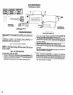
ASSEMBLY
a.
Assembly of the valve assembly (45174) will be the reverse of
the disassembly procedure. Lubricate all “0” rings with ARO
36460 “0” ring lube, or equivalent, upon assembly. It is recom-
mended that “0” rings be replaced whenever a part contain-
ing
"0"
rings has been disassembled. Be sure gaskets are in
good repair and assembled in the proper position.