


RM3 SERIES BACKREFLECTION METER
USER’S MANUAL
10112341 Rev 002 Page 12 of 39
Backreflection Measurements
Reflections in optical systems can come from a number of sources. Primary sources include
the fiber (Rayleigh backscatter) and Fresnel reflections that occur at the planar junction of two
materials having different refractive indices, for example, connector and fiber endfaces,
splices, bulk optic interfaces, and detector surfaces.
Typically only Fresnel reflections are significant because transmitters are relatively insensitive
to distributed reflections such as Rayleigh backscatter. Backreflection caused by Rayleigh
backscatter varies with the length and type of fiber, and is only significant when measuring
components with backreflections below -40 dB or with very long pigtails (multimode). However,
Rayleigh backscatter can be a large contributor to backreflection in installed systems or when
using long fiber.
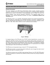
The internal switch and coupler of the RM meter enable the meter to measure the internal light
source signal (P
in
), the signal offset with no light (P
dark
), and the total signal level from internal
and external backreflections (P
br
).
The RM meter first calculates the total backreflection from internal and external sources (BR
tot
),
using the following equation, where CAL is the factory-set calibration factor of the meter:
BR
tot
= 10 log (P
br
- P
dark
)/(P
in
- P
dark
) - CAL [dB]
The backreflection from external sources (BR) is then calculated using the following equation,
where BR
0
is the stored value of the total backreflection up to the device under test (DUT), and
User CAL is the user-set calibration factor:
BR = 10 log (10
BR
tot
/10
- 10
BR
0
/10
) + User CAL [dB]
The RM meter then displays the value of BR.
The BR measurement takes approximately one second to complete. Before this is done, the
P
in
and P
dark
measurements are completed in approximately four seconds, during which time
the backreflection display is locked and the light from the output port is blocked. The values
are then updated every minute.
Loss and Power Measurements
The RM meter is equipped with a front-panel InGaAs detector for relative power (loss) and
absolute power measurements. (Absolute power is referred to as power in this manual; relative
power is always referred to as relative power.) Because the meter is capable of storing the
dark signal from the detector, high-accuracy power measurements as low as -80 dBm for the
single mode model (and –60 dBm for the multimode model) can be obtained.
When making power measurements, the RM meter first measures two signals: the total signal
level (I
tot
) and the dark signal from the detector (I
D
). The RM meter then calculates the power
measurement using the following equation, where CAL is the factory-set calibration factor and
User CAL is the user-set calibration factor:
P = 10 log (I
tot
- I
D
) + CAL + User CAL [dB]