RM3 SERIES BACKREFLECTION METER
USER’S MANUAL
10112341 Rev 002 Page 38 of 39
On power-up, the RTS and DTR signals on the interface connector go positive, indicating that
the interface is ready to communicate. The software on the controlling computer must enable
the RTS line. The interface controller waits for the CTS line to go positive before the
measurements are transmitted. The DCD line must go positive in order for the controlling
computer to receive commands from the meter.
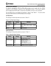
The meter responds to single character commands sent on the serial interface. The characters
must be sent individually, without a message terminating sequence such as <CR> (carriage
return) or <LF> (line feed). The meter acknowledges each character that is sent with a
character or a measurement reading.
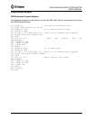
The command G initiates the transmission of a measurement. The meter returns the most
recent measurement. The transmission also includes the wavelength at which the
measurement was made and the characters <CR> <LF>.
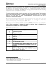
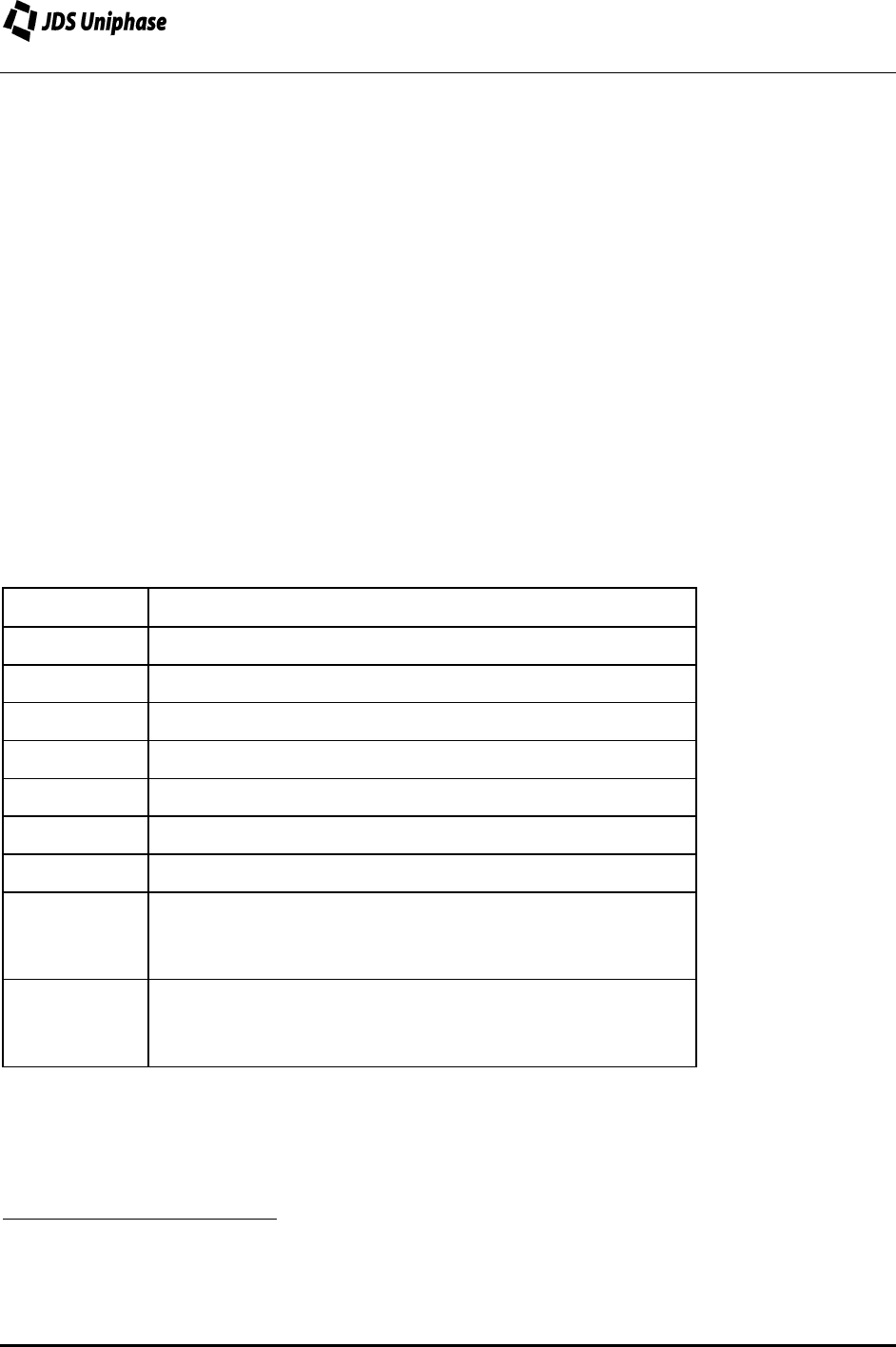
The character commands that control the meter via the RS232 serial interface port are listed in
Table 9. When a command is accepted, the letter Y is returned. When a command is not
recognized or not accepted, the letter X is returned.
Table 9: Character Commands
Command Action
B Display backreflection
A Display absolute power
R Display relative power
SStore BR
0
1
C Clear BR
0
1
DStore I
D
2
0 Set relative power to zero
3
3 Set wavelength to the laser connected to the first LED
on display (eg. Model RM3750, first laser=1310nm. See
Figure 3)
5 Set wavelength to the laser connected to the second
LED on display (eg. Model RM3750, second
laser=1550nm. See Figure 3)
1
Valid in Backreflection mode only.
2
Valid in Absolute Power and Relative Power modes only.
3
Valid in Relative Power mode only.


