


RM3 SERIES BACKREFLECTION METER
USER’S MANUAL
10112341 Rev 002 Page 37 of 39
Programming Guide
RS232 Serial Interface
The RM meter is equipped with an RS232 serial interface. Through the RS232 connection, the
user can download measured values of backreflection, loss, and power to a computer or
printer. The RM meter can also use an IEEE 488 parallel interface through the external RS232-
to-IEEE 488 converter (described in the RS232-GPIB Converter section).
The RS232 serial interface is configured as data terminal equipment (DTE). The data protocol
is set to 2400 baud, ASCII character code with eight bits per character, two stop bits, and no
parity bit.
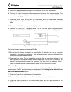
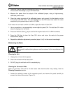
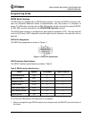
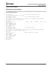
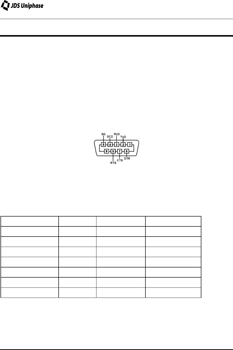
RS232 Pin Assignment
The RS232 pin assignment is shown in Figure 11.
Figure 11: RS232 Pin Assignment
RS232 Interface Specifications
The RS232 interface specifications are listed in Table 8.
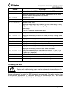
Table 8: RS232 Interface Specifications
Name Symbol Pin Number Signal Direction
Transmitted data TxD 2
→
Received data RxD 3
←
Request to send RTS 8
→
Clear to send CTS 7
←
Data carrier detect DCD 4
←
Data terminal ready DTR 6
→
Signal ground SG 5
↔
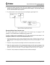
To connect the RM meter to the serial port of a computer:
1. Attach a straight-through RS232 cable to the computer and the RS232C port at the back of
the meter.