


11
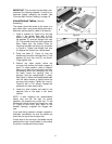
IMPORTANT: The conveyor belt has been over-
tensioned for shipping purposes. It must be re-
tensioned before operating the sander! See
“Conveyor Belt Tension/Tracking” on page 16.
Infeed/Outfeed Tables (Optional
Accessory)
The sander should be bolted to the stand or a
work table when using these table extensions.
Maximum working load of a table is 35 pounds.
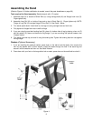
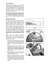
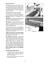
1. Install a bracket (A, Figure 8) to the two
holes in the sander base with a 9/16”
wrench, using two hex cap screws (B), two
flat washers (C) and two flanged lock nuts
(D). The bracket should be flush against the
base. Make sure the slotted holes for
mounting the table are facing up, as shown
in Figure 8. Tighten the flanged lock nuts
(D) against the inside of the sander base.
2. Place the table (E, Figure 8) over the
bracket and insert four carriage bolts, (F) flat
washers (G) and hex nuts (H), as shown.
Finger tighten only.
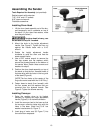
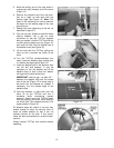
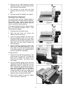
3. Position the table slightly below the
conveyor belt surface for proper support of
stock. To check position, place a straight-
edge on one side of the conveyor bed under
the sanding drum and extending out over
the table. Lower the sanding drum to
securely hold the straight-edge in place.
See Figure 9. Raise the infeed/outfeed table
until the table surface is slightly below the
conveyor belt surface. Tighten hex nuts (H,
Figure 8) with a 7/16” wrench. Repeat this
procedure for other side of table.
4. Install the other bracket and table to the
opposite side of the base in the same
manner.
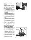
NOTE: If after adjusting the infeed/outfeed
tables, they are still too high for proper
operation, the bracket may not be “set.” To set
the bracket, slightly loosen the flanged hex nuts
(D, Figure 8) and firmly push down on the
bracket. Securely re-tighten the flanged hex
nuts.
If the stock being sanded is bowed, warped or
otherwise inconsistent, be sure the tables are
lower than the top of the conveyor bed.
If stock slips on the conveyor, the tables may be
positioned too high. Lower tables to allow stock
to remain in contact with the conveyor.
Figure 8
Figure 9