


18
Fine-Tuning Drum Alignment
(for sanding boards wider than the drum)
NOTE: Perform this alignment after you are
familiar with sander operation. This is an
operational test.
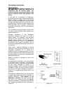
When sanding boards wider than the drum,
drum alignment is critical and must be exactly
level to slightly high on the outboard end to
prevent ridges from forming on the board.
Always check this on a piece of scrap wood, as
follows, before sanding the work piece.
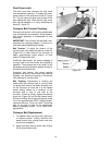
1. Test alignment with scrap wood roughly 6
inches wide and 20 to 30 inches long. Install
abrasive, turn on sander, and pass the
board through the sander sideways so that
the end of the board extends beyond the
end of the drum.
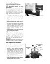
2. Without changing drum height, rotate the
board 180° and sand the same side.
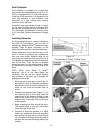
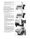
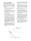
3. If a ridge is visible where the drum overlaps,
loosen the four screws (A, Figure 27) and
raise the outboard end of drum by turning
the fine tune adjustment knob (B, Figure 27)
slightly clockwise. Re-tighten the four
screws.
4. Repeat process until the ridge is eliminated,
and the entire board is sanded.
NOTE: Keep track of how many revolutions of
the fine tune knob are needed to change drum
alignment for wider (over 16”) sanding. When
sanding narrow stock (less than 16”) loosen the
four screws (A, Figure 27) and turn fine tune
adjustment knob counterclockwise same
amount as initial wide sanding until drum is
again parallel.
Important: Only turn fine tune adjustment knob
when all four screws (A, Figure 27) are loose.
Drum Height Control Adjustment
If the height control mechanism does not
operate easily or smoothly, or there is excessive
vertical movement or deflection of the drum
carriage, perform the following adjustments:
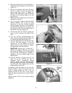
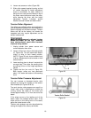
1. With a 1/8” wrench, adjust all four studs by
tightening the lock nuts (Figure 28), then
loosening them 1/8 to 1/4 turn. If the lock
nuts are set too tight, height control will not
operate easily. If the lock nuts are too loose,
excessive deflection of the outboard end of
the drum carriage will result.
2. Apply lubricant to front and rear areas of
motor mount slide.
3. Push height adjustment handle (Figure 28)
downward to set firmly on housing.
Figure 27
Figure 28