


13
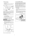
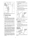
Figure 14: Loosening pulley set screws to allow the
adjustment of pulley on arbor shaft.
8.0 Machine setup
8.1 Basic setup
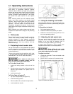
1. Position the machine where it will be located on
the shop floor. When positioning the machine,
consider the type of work which will be done on it
so you allow sufficient room not only for the
workpieces, but also for service to the machine.
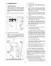
2. Open the door in the base of the machine and,
using the holes in the base as a template, mark
the floor for the position of the hold-down bolts.
3. Move the machine to expose the hold-down bolt
marks and install anchors for the hold-down
bolts.
4. Put the machine back over the hold-down
anchors and bolt the machine securely to the
shop floor. THIS MUST BE DONE FOR SAFE
OPERATION OF THE MACHINE.
5. Establish an electrical service connection to the
machine. This will vary according to the model
purchased. ALL ELECTRICAL CONNECTIONS
SHOULD BE MADE BY A QUALIFIED
ELECTRICIAN WHO IS FAMILIAR WITH YOUR
STATE AND LOCAL CODES. Many models of
these machines make use of high voltages which
pose a significant risk of serious injury or DEATH
if proper knowledge and precautions are not
used. Electrical instructions are included in
section 9.0 Electrical connections.
6. Machines with belts are shipped with the belts in
slack condition. During the electrical hookup
phase of machine setup, the belt will have to be
tightened and checked for tracking. See the Belt
Replacement section for instructions on this
procedure.
8.2 Disc table angle adjustment
1. Disconnect power to the machine to prevent
accidental start-ups.
2. Loosen the table locking knobs on either end of
the table.
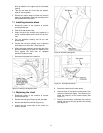
3. Using a machinist's square against the table and
disc, set the table at exactly 90°
to the disc (See
Figure 15).
4. Tighten the table locking knobs.
5. Check the pointer. If it is not exactly on the zero
mark, loosen the pointer attaching screw, adjust
the pointer, and retighten the screw.
6. Reconnect the power to the machine.
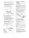
Figure 15: Using a square to check the disc table
scale.
8.3 Disc table miter parallelism
adjustment
1. Disconnect power to the machine to prevent
accidental start-ups.
2. Set the table angle to zero.
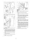
3. Place a scale or adjustable machinist's square
against either the left or right edge of the disc
face and measure the distance to the miter slot
edge (See Figure 16).
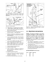
Figure 16: Using an adjustable square to set the table
parallelism.