


15
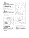
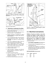
Figure 20: Location of adjustment (socket head)
screws and pointer attachment screw for table angle
adjustment.
Figure 21: Locations of stop lugs and stop bracket for
zero and 45° table positions.
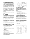
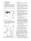
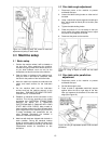
8.7 Adjusting or replacing the platen
1. Disconnect the electrical power to the machine to
prevent accidental start-ups.
2. Remove the top cover, side guard and belt as
outlined in section 7.1, Belt replacement.
3. Remove the table by unscrewing the locking
handling and lifting the complete table assembly,
from the machine.
4. If you are replacing the platen, remove the three
screws that hold it to its mount -- then install the
new platen and replace the mounting screws
finger tight.
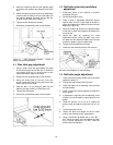
5. If you are only adjusting the platen, loosen the
three mounting screws to allow adjustment.
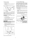
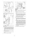
6. Using a straight edge as shown in Figure 22,
adjust the platen height until it is 1/32 inch higher
than the crown of both the drive and idler drums.
7. Tighten the platen adjustment screws.
8. Reinstall the table and belt.
9. Check and adjust, if necessary, the tracking of
the belt according to instructions in section 7.1,
Belt replacement.
10. Reinstall the guards and covers.
11. Check and adjust the table angles and miter slot
squareness according to table adjustment
instructions in this manual.
12. Reconnect the electrical power to the machine.
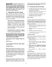
Figure 22: Method for adjusting height of platen
above drive and idler drums.
9.0 Electrical connections
Caution: JET sanders are available in a wide variety
of electrical configurations to meet the needs of the
purchaser with respect to power available and
compliance with electrical codes. Each machine is
tested at the factory for operation before shipment
and the power cord is tagged with the power
requirements for the machine, as shipped.
HOWEVER, before attempting any electrical hookup,
you should be certain:
1. The electrical characteristics of the service
branch match the requirements of the motor.
2. The service branch is equipped with wires of the
required gauge or size.
3. The branch circuit intended for the machine is
protected with a time delay fuse or circuit breaker
with rated amperage just slightly greater than the
full load current of the motor.
MOTOR AMPERAGE full load current
Phase Voltage Amperage
1 115 20
1 220 10
3 220 5.2
3 440 2.6