


14
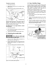
4. Move the measuring device to the opposite edge
of the disc and measure the distance to the miter
slot.
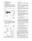
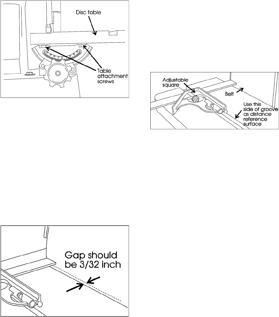
5. Adjust the table by loosening the four attachment
screws under the table, then move the table until
the distance between the miter slot and the disc
is equal on both sides (See Figure 17).
6. Tighten the four attachment screws.
7. Reconnect the electrical power to the machine.
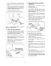
Figure 17: Table attachment screws – loosen to
adjust miter groove parallelism.
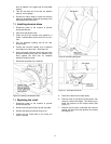
8.4 Disc table gap adjustment
1. Using a scale, check the gap between the edge
of the table and the face of the disc. It should be
very close to 3/32 inch. If it is much more or less
than that distance, adjust it as follows:
2. Disconnect the electrical power to the machine.
3. Using the access hole on the top of the disc
guard, locate and loosen the two set screws that
secure the disc to the shaft.
4. Slide the disc in or out along its shaft until the
table-to-disc gap is 3/32 inch (See Figure 18).
5. Tighten both set screws.
6. Reconnect the electrical power to the machine.
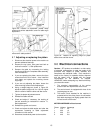
Figure 18: Table-to-disc gap measurement.
8.5 Belt table miter slot parallelism
adjustment
1. Disconnect power to the machine to prevent
accidental start-ups.
2. Set the table angle to zero.
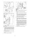
3. Place a scale or adjustable machinist's square
against either the left or right edge of the belt or
platen and measure the distance to the miter slot
edge (See Figure 19).
4. Move the measuring device to the opposite edge
of the belt or platen and measure the distance to
the miter slot.
5. Adjust the table by loosening the three
attachment screws under the table, then move
the table until the distance between the miter slot
and belt or platen is equal on both sides.
6. Tighten the three attachment screws.
7. Reconnect the electrical power to the machine.
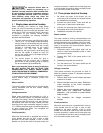
Figure 19: Using an adjustable square to check and
set miter slot parallelism on the belt table.
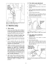
8.6 Belt table angle adjustment
1. Loosen the table locking handle and tilt the table
upward to about 15°.
2. Flip out the stop bracket (See Figure 21).
3. Lower the table until its adjusting screw touches
the stop bracket.
4. Place a machinist's square against the table and
belt or platen.
5. If adjustment is required, turn the adjusting screw
(Figure 20) until the table is exactly square to the
platen.
6. Check the pointer. If it is not on 0°, loosen the
pointer screw and adjust the pointer until it is on
0°.
7. Tighten the pointer screw.
8. Loosen the table lock handle and tilt the table
until its stop contacts the 45° stop position.
9. Using a machinist's protractor set on 135° (90° +
45°) adjust the screw until the table and platen
are in correct adjustment. DO NOT reset the
pointer after this operation.