


9
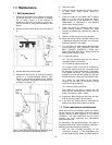
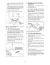
To adjust to horizontal:
1. Unlock both lock bolts.
2. Move arm to horizontal until it contacts its stop.
(See Figure 3.)
3. Tighten both lock bolts and replace arbor cover.
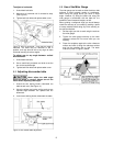
Figure 3: Arm at horizontal – note that the table is
removed. The table may be removed or left in
position, and may also be set to any angle to allow
horizontal sanding of various angles.
To adjust arm to any angle between vertical
and horizontal:
1. Unlock both lock bolts.
2. Use a machinist's protractor and level to set the
arm to the required angle.
3. Tighten both lock bolts and replace arbor cover.
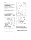
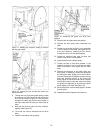
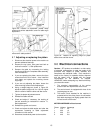
6.5 Adjusting disc sander table
Never adjust the table angle
while the sander is running. Always turn off the
motor before adjusting table angle.
1. Unlock the two locking knobs underneath the
table at each end. (See Figure 4.)
2. Using the pointer and scale, set the angle to any
required angle between 20° upward and 45°
downward.
3. Lock the two locking knobs underneath the table.
Figure 4: Disc sander table adjustment
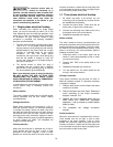
6.6 Use of the Miter Gauge
The miter gauge can be used on either the disc or belt
surfaces to sand accurate angles on workpieces.
When using the gauge alone, you sand a single
angle. However, by tilting the table and using the
miter gauge in combination with the table tilt, it is
possible to sand compound angles, as well.
When grinding a compound angle you should always
check the accuracy of your setup by sanding a piece
of scrap material before doing any finish sanding on
the actual workpiece.
1. Set the angle you wish to sand using the scale on
the miter gauge.
2. Tighten the miter gauge securely so the miter
reference surface will not move while you are
sanding.
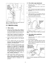
3. Place the workpiece against the miter reference
surface and slide it along the reference surface
and into the sanding disc or belt. The basic
method is shown in Figure 5, below.
Figure 5: Use of the miter system