


10
9.0 Setup and assembly
9.1 Shipping contents
1 Molder/Planer
1 Dust Chute
2 Extension Roller Assemblies
1 Accessory Package, containing:
1 Handle Assembly
1 10/12mm Wrench*
1 11/13mm Wrench*
1 Screwdriver*
1 3mm Hex Wrench*
1 4mm T-Handle Hex Wrench*
1 5mm Hex Wrench*
1 Knife Setting Gauge*
1 Molding Cutter Gauge*
1 Feed Roller Adjustment Wrench*
1 Brass Bar*
1 Video
1 Hardware Bag #2 (p/n MHD-17S-A)
1 Operator’s Manual
1 Warranty Card
* included in Hardware Bag #1 (p/n MHD-17S)
Read and understand all
assembly instructions before attempting
assembly. Failure to comply may cause serious
injury.
9.2 Unpacking and cleanup
1. Finish removing all contents from the shipping
container. Do not discard any shipping
material until the planer/molder is set up and
running properly.
2. Inspect contents for shipping damage. Report
damage, if any, to your distributor.
3. Compare contents of shipping carton with the
contents list in this manual. Report shortages,
if any, to your distributor.
4. Clean all rust protected surfaces with a mild
solvent or kerosene. Do not use lacquer
thinner, paint thinner, or gasoline; these will
damage painted surfaces.
5. To prevent rust, apply a light coating of paste
wax to the table surface.
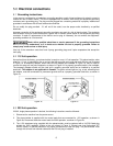
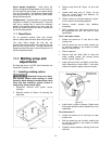
9.3 Assembly
1. Remove dust hood. Check gib screws on
cutterhead for tightness. Reinstall dust hood.
Note: Recheck after five minutes of operation.
Recheck again after every 2 hours of use.
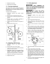
2. Attach the handle to the post with a hex socket
cap screw.
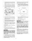
3. Attach the top side of dust chute with three
M5x10 machine screws, and three M5
washers.
4. Attach lower section of dust chute with three
M6x8 machine screws, and three M6 washers.
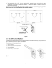
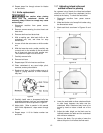
5. Mount extension roller assembly to the middle
table with four M8x12 hex cap bolts, and four
M8 flat washers. The frame is adjustable using
these bolts.
6. Use a straight edge to make sure rollers are
level with middle table.
7. The first roller is adjustable by loosening the
hex cap bolts that hold the roller on the frame
supports.
8. Repeat steps 5-7 for opposite side roller
assembly.
Never run machine with dust
hood loose or removed. Failure to comply may
cause serious injury.
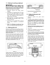
10.0 Adjustments: Planing
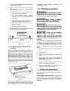
10.1 Depth of cut
Maximum depth of cut is 1/8”
up to 5-1/2” wide, and 1/16” on stock over 5-
1/2” wide. Trying to cut more in one pass will
cause stress on machine and could damage
cutterhead.
Thickness planing refers to the sizing of lumber to
a desired thickness while creating a level surface
parallel to the opposite side of the board.
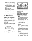
The quality of thickness planing depends on the
operator’s judgment about the depth of cut. Depth
of cut depends upon the width, hardness,
dampness, grain direction, and grain structure of
the wood.
The maximum thickness of wood that can be
removed in one pass is 1/8” on wood up to 5-
1/2” wide and 1/16” on wood wider than 5-1/2”.
When planing hard wood, take light cuts or plane
wood in thin widths.
Make a test cut when working with a new type of
board or different kind of operation. Check the
accuracy of the test cut before working on the
finished product.
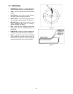
10.2 Adjusting depth of cut scale
Use caution when placing
hands near cutterhead. Knives are extremely
sharp. Failure to comply may cause serious
injury.
1. Take a test cut.