


11
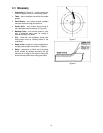
2. Measure the cut piece.
3. Adjust pointer accordingly.
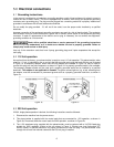
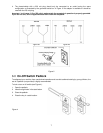
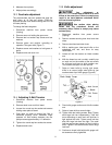
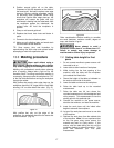
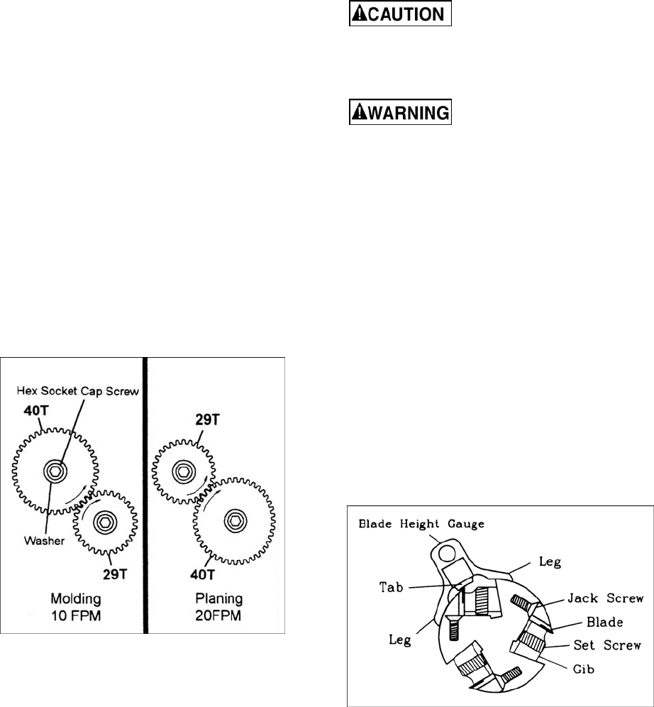
10.3 Feed rate adjustment
The planer/molder has two speeds that feed the
work piece, at 10 feet per minute (FPM) for
improved surface finish when molding and 20 FPM
for faster planing.
To change the feed rate gears:
1. Disconnect machine from power source
(Unplug).
2. Remove acorn nut holding the gear cover.
3. Remove two hex socket cap screws and two
washers.
4. Remove gears and position according to
operation. See gear chart (Figure 7).
5. Replace screws and washers to hold gears in
place.
6. Replace cover and acorn nut.
Figure 7
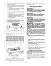
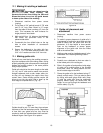
10.4 Adjusting V-Belt Tension
1. Disconnect machine from power source.
(Unplug)
2. Remove stand cover on left of stand.
3. Loosen four round cap hex socket slot screws
holding motor plate to stand.
4. Push down on motor to tension belt. Belt is
tensioned properly when moderate finger
pressure on belt midway between the two
pulleys causes approximately 1/4” deflection.
5. Tighten four round cap hex socket slot screws.
6. Replace stand cover.
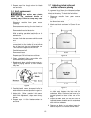
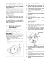
10.5 Knife adjustment
Any adjustment or
replacement of knives must be done to all three
knives at the same time. Failure to comply may
result in an out-of-balance cutterhead which
will lead to bearing failure.
Use caution when placing
hands near the cutterhead. Knives are
extremely sharp. Failure to comply may cause
serious injury.
1. Disconnect machine from power source
(Unplug).
2. Remove screws securing dust hood and dust
chute.
3. Remove dust hood and dust chute.
4. With a marking pen, label each knife on the
cutterhead one, two, and three for easy
identification.
5. Loosen all lock bar screws on blade number
one.
6. With the brass bar and a mallet, carefully tap
on each end on the outside of the set screws
for all three lock bars on knife number one.
This loosens the taper fit of the lock bar.
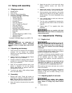
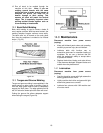
7. Raise or lower knife by turning jack screw.
Knife is at correct height when knife tip just
touches center tip of knife gauge (Figure 8).
Figure 8
8. Place knife gauge at other end of knife number
one.
9. Raise or lower knife to correct height.
10. Tighten knife bar locking screws. Note: Tighten
each large lock bar independently. Take half
turns alternating on each end until lock bar is
tight against the knife. Tighten small lock bar
after two large lock bars are tight. The small
lock bar requires two spacers to firmly hold the
knife. Tighten in the same manner as the large
lock bars.
11. Continue to check knife height with gauge until
set screws are firmly tightened.