


12
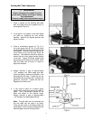
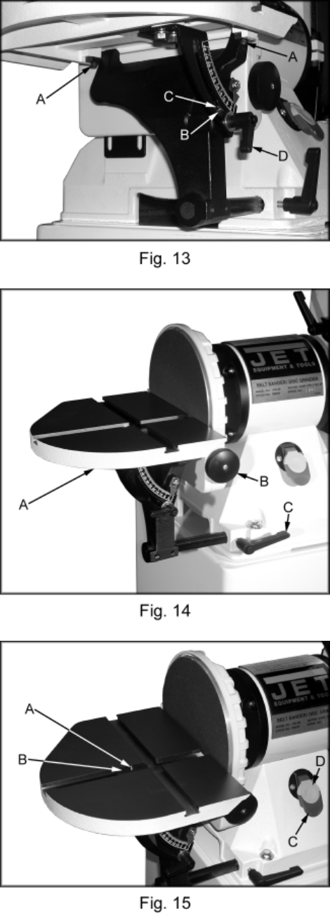
4. If the miter slot is not parallel loosen the two
socket head cap screws (A, Fig. 13) and
adjust for parallel. Tighten the two screws
when the adjustment is complete.
5. Always maintain a gap of approximately
1/16” between the table edge and disc.
Once the table is square and parallel to the
disc adjust the 90° stop. Loosen hex nut (B,
Fig. 13) and tighten the set screw (C, Fig.
13) until it contacts the trunnion. Tighten
hex nut.
6. If the pointer does not line up with the “0” on
the scale loosen the screw and adjust for “0”.
Tighten the screw.
7. The table can be tilted between 0°-45° by
loosening the handle (D, Fig. 13) and tilting
the table to the desired angle. Tighten the
handle. Always maintain a gap of
approximately 1/16” between the table edge
and disc.
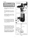
Note: The belt table can be removed and
the disc table can be used in its place.
There are two holes in the base below the
sanding belt that will accommodate the disc
table’s support rod and locking handle.
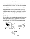
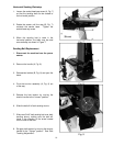
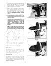
Sanding Disc Replacement
1. Disconnect machine from the power
source.
2. Loosen the handle (C, Fig. 14) and remove
the table assembly (A, Fig. 14).
3. Turn the knob (B, Fig. 14) and open the
door.
4. Remove old sanding disc by striping from
wheel. Make sure the disc plate is clean.
5. Press the new disc firmly into place.
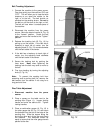
Center Point
The center point (A, Fig. 15) provided with the
sander can be used for sanding circles. The
center point can be locked in position by
tightening the set screws (B, Fig. 15).
On/Off Switch
The machine can be turned on by moving the
switch (C, Fig. 15) to the up position. The key
(D, Fig. 15) can be removed when the machine
is in the off position. With the key removed the
switch will not operate.