


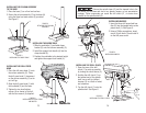
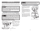
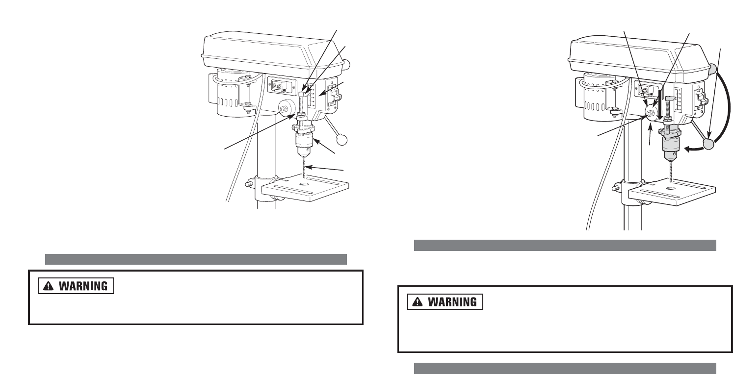
3. Turn the spring housing (5) counter-
clockwise to increase the spring ten-
sion or clockwise to decrease the
spring tension.
4. Turn nut (4 - inside) until it contacts
the spring housing (5). Back nut (4)
out 1/4 turn and tighten it against
nut (3 - outside) to hold the spring
housing in place.
5. IMPORTANT: The inside nut (4)
should not touch the spring housing
(5) after it has been tightened.
CORRECT DRILLING SPEEDS
The correct drilling speed is determined by type of material being drilled, the size of
the hole, the type of the drill bit or cutter, and the desired quality of the hole.
Always use the recommended speed for the drill bit and
for the type of materials the workpiece is made of. If you have any questions
as to the proper speeds or types of materials, contact Alltrade customer
service at 1-800-590-3723.
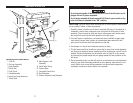
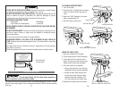
WORKING WITH WOOD
Twist drills, although designed for drilling metal, can also be use for drilling wood.
However, it is recommended that machine spur bits or wood-boring bits be used for
wood projects. These bits cut a flat bottom hole and are designed to remove to eas-
ily remove wood chips. DO NOT USE hand bits designed for a hand-operated drill
brace. These bits have screw tips and at the speeds used by the drill press, they
would rapidly engage the workpiece and spin it around violently.
For through boring, line up the spot where the hole is to drilled with the hole in the
worktable. This permits the drill bit to pass cleanly through the workpiece without
damaging the worktable. Scribe a vertical line on the front of the column and match-
ing marks on the table bracket and the drill press head so that the table and drill
press can be clamped in the center position at any height.
To prevent splintering on the bottom of the workpiece, clamp a scrap piece of wood
beneath the workpiece and allow the drill bit to enter it resulting in a clean hole on
the workpiece. This also protects the point of the drill bit.
23
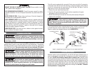
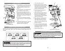
1. Insert drill bit (2) into drill chuck.
2. Lower the spindle (3) until the pointer
(4) is in line with the mark on the
scale (5).
3. Tighten the lock screw (6).
4. Return the spindle (3) to the up posi-
tion.
5. Place the workpiece on the drill press
table and securely clamp it in place.
6. Raise the drill press table until the
workpiece just touches the end of the
drill bit (2).
7. Drill a test hole and check the depth.
Make any adjustments as necessary.
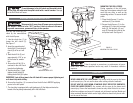
ADJUSTING THE SPINDLE RETURN SPRING
Disconnect drill press from AC power source and ensure
the “ON/OFF” switch is in the “OFF” position. Failure to adhere to this warn-
ing could cause severe, permanent injury to the operator.
The spindle return spring (1) is automatically returned to its upper position when
the pinion shaft handles (2) are released. It is recommended that the pinion shaft
handles (B) be allowed to return to the upper position slowly. DO NOT LET GO OF
THE HANDLES after the hole has been drilled. This action will cause excessive wear
and tear on spindle return spring. To adjust the spindle return spring, See Figure 15
and follow the steps below:
1. Loosen the two nuts (3 and 4). Ensure the housing stays engaged with the
head casting.
2. While firmly holding the spring housing (5), pull out the housing until the boss
is engaged with the next notch on the housing.
1
5
2
3
4
FIGURE 16.
ADJUSTING SPINDLE
RETURN SPRING
FIGURE 15.
DRILLING HOLES TO SPECIFIED DEPTHS
6
1
4
5
3
2