


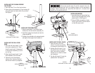
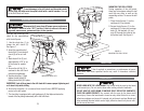
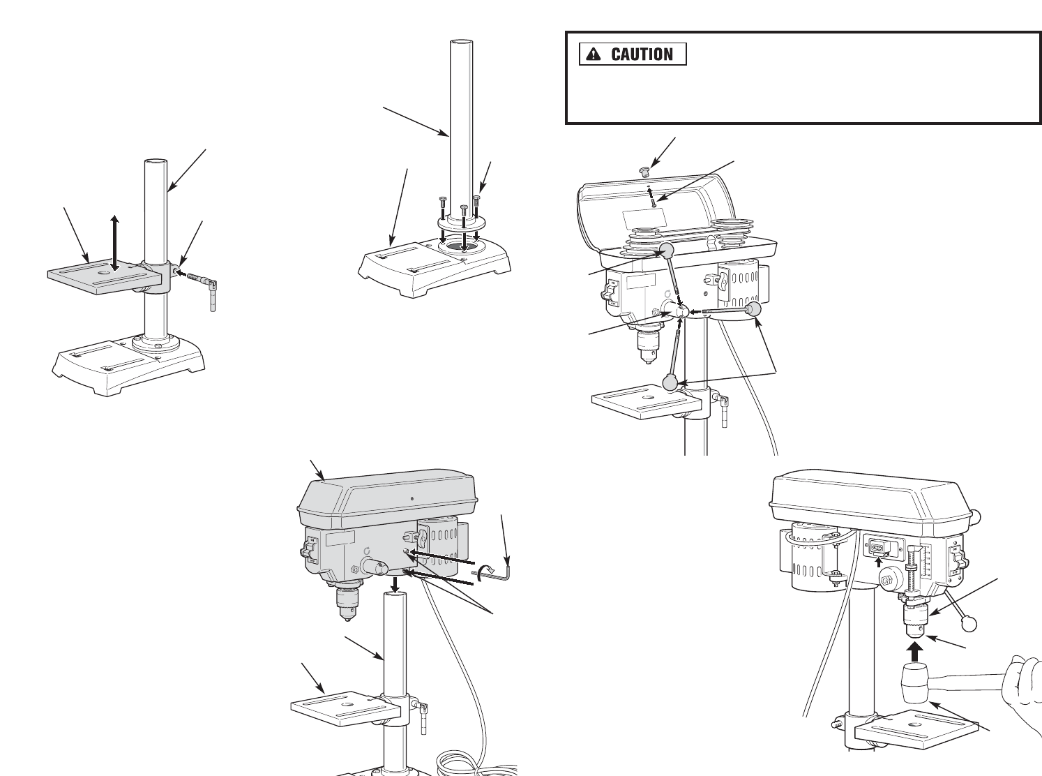
Ensure the spindle taper (Q) and the tapered hole in the
drill chuck (R) are clean and free of any grease, lacquer, or rust preventative
coatings. These compounds can cause the drill chuck (R ) to seize when
installed on the spindle shaft (Q).
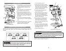
INSTALLING THE DRILL CHUCK
1. Open the jaws of the drill
chuck (1) as wide as possible
by turning the chuck sleeve (2).
2. Holding the drill chuck (1) on
the tapered end of the spindle
shaft, use a soft tip (rubber)
hammer (3) or a block of wood
and a hammer.
3. Tap the drill chuck (1) onto the
spindle shaft. See Figure 6.
1413
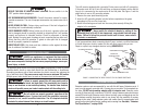
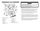
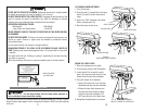
INSTALLING THE COLUMN ASSEMBLY
TO THE BASE
1. Place the base (1) on a firm level surface.
2. Secure the column assembly (2) to the base (A)
using the three hex-head screws (3) provided.
See Figure 2.
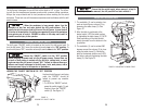
INSTALLING THE DRILL PRESS
HEAD
1. Place the drill press head (1) onto
the column assembly (2). Press
the drill press head (1) downward
on the column assembly (2) as far
as it will go.
2. Align the drill press head (1) with
the worktable (3) and the base.
3. Tighten the two head locking
screws (4) as shown in Figure 4,
with the hex-wrench (5) supplied.
INSTALLING THE WORK TABLE
1. Slide the worktable (1) and table clamp
bracket (2) onto the column assembly (3).
2. Install the support lock handle (4) into the
clamp bracket (2).
3. Position the worktable to the desired height
and tighten the support lock handle (4).
1
2
3
2
3
FIGURE 2.
ATTACHING THE COLUMN
ASSEMBLY
FIGURE 3.
INSTALLING THE WORK TABLE
INSTALLING HANDLES
1. Insert the three drill press feed han-
dles (2) into the tapped holes on the
pinion shaft (1). See Figure 5.
2. Using a Phillips screwdriver, insert
screw (4) into knob (3) and install it
on the drill press cover.
1
2
3
1
2
5
FIGURE 4.
INSTALLING THE DRILL PRESS
AND MOTOR
FIGURE 5.
INSTALLING HANDLES
4
2
3
4
1
2
1
3
FIGURE 6.
INSTALLING THE DRILL CHUCK